1
Introduction
This document
presents an overview of available options in EMTP®-EMTPWorks. More
details can be found in other documents and help tools.
Since the top view
to all EMTP® simulations is the graphical user interface EMTPWorks,
the main objective of this document is to show how required network data can be
assembled and what is the expressive power of EMTPWorks for managing EMTP®
simulations.
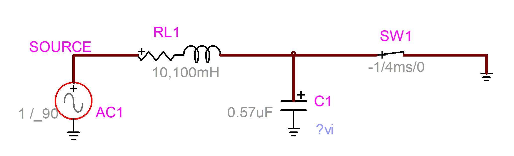
The picture of Figure 1 is showing a simple circuit assembled in EMTPWorks. The various parts, also called devices, are dragged in from the parts library (Parts palette shown on the right hand side by default) into the design, placed and connected using signals.
EMTPWorks allows working at different levels: from simple designs to extremely large designs and from simple drawings to customized drawings.
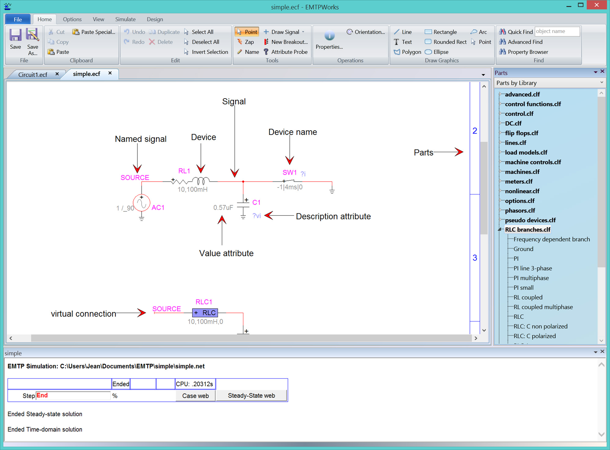
The design shown in Figure 1 has a top level circuit. This is called a top circuit. A design can be organized on one or more pages: design pages. The design may also have one or more subcircuits. Subcircuits may also contain one or more subcircuits. The circuits are the children of the design.
The top part of the
circuit above is shown in Figure 2. All devices, signals and names can be clicked
and right-clicked for entering data or controlling other aspects. The circuit
itself also has a right-click menu.
Right and bottom
elevator bars can be used to move around a large circuit. The Zoom tool (View
ribbon) can be used to zoom and unzoom. The useful zoom keyboard shortcuts are
CTRL-SHIFT-E (enlarge) and CTRL-SHIFT-R (reduce).
Panning is available
by holding the CTRL key and clicking and holding anywhere in the circuit page.
The users can also select this option directly from the Zoom tool found in the
View ribbon.
The size of the
circuit page can be changed using the menus in “Options>Design”. The default
size is the size taken from the connected printer.
The devices are
given an automatic visible name. This name can be changed by double-clicking on
the name. The signals are given an automatic name. The user can change a signal
name by right-clicking on the signal name or by selecting the Name tool (see
Home ribbon Tools section) and clicking on the signal or signal name. Signal
naming is generally less useful than device naming. It should be only used for
creating some specific connections by name as discussed further in this
document. Signal naming is not a good practice in a graphical user interface.
EMTPWorks has internal automatic methods for maintaining internal signal names
and connectivity.
Meaningful naming is
key to making designs decipherable and verifiable by self and by others.
Meaning is added when renaming key devices to indicate more precisely their
specific function in the diagram.
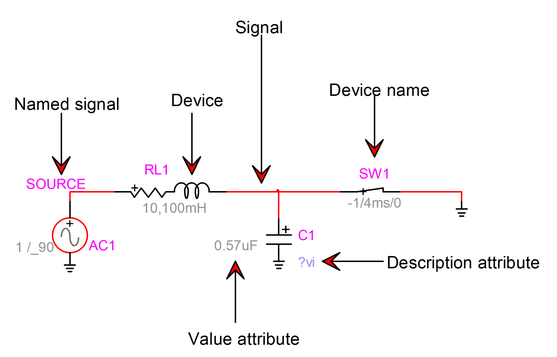
Figure
2
Simple first example
After creating the
design circuit of Figure
2 the following steps must be followed to run a
simulation:
1
Enter data
into devices (double-click each device) according to the simulated circuit.
2
Select the
menu “Simulate>Advanced>Simulation Options” and enter the simulation
parameters.
3
Push the
Run button in the Simulate ribbon to start the simulation.
The simulation
progress panel (also called wait bar) is appearing at the bottom of the design
in Figure
1.
When the simulation
ends, simulation results saved as waveforms can be visualized using waveform
visualization tools. The program also generates output webs, that can be accessed
from the wait bar (see “Case web” and “Steady-State web” buttons in Figure
1.
The default waveform
visualization and analysis tool is called ScopeView. It can be started by
clicking on the command button “View Scopes with ScopeView” found in the Scopes
group of the Simulate ribbon.
Another waveform
visualization tool is available by clicking on the “View Scopes with MPLOT”
button found in the same Scopes group. The MPLOT command is also available from
the right-click menu (right-click on an empty space) of the circuit.
When the Run button
is pushed, EMTPWorks creates a Netlist file and submits it to the EMTP®
computational engine. The Netlist file contains only specific information
needed by EMTP® to simulate the design. The entire design with all
other data including geographical positions, is saved into a design file with
the extension “.ecf”.
More details on
input/output files can be found in the help section of the “Simulate>Advanced>View
Output Files” panel.
The help section of
the menu “Simulate>Advanced>Simulation Options” is a starting point for
learning about EMTP® simulation methods. Each device is also given
its own help section. The best approach for learning is to start by reading the
current document and then by exploring available menus and options. Help
hyperlinks and tabs are available everywhere.
In addition to a
design file, EMTPWorks can be used to visualize ASCII files. It also has a JavaScript
command console and a “Report Script” language.
2
Devices
Devices are dragged
in from the Parts Library (on the right hand side of EMTPWorks main window, see
Figure
1) and placed on the Design circuit at the
desired location. The Parts Library can be turned on and off from the View
ribbon (View>Panels>Parts Library). Each device has a default orientation
in its library. The orientation can be changed after placement in the circuit. The
initial orientation can be also changed from the Home ribbon menu
Operations>Orientation.
Once a device is
positioned in a circuit it can be moved around using the mouse key or the
keyboard arrow keys. When a device moves it tries to maintain existing connectivity,
but this is a complex task and the user may have to redo connectivity manually
under some conditions.
A device may have no
pins, one or more pins. A two-pin device is shown in Figure
3. The left-pin or the pin close to the “+” sign
is also called a k-pin. The right-pin or the other pin, is also called an
m-pin. The plus “+” sign is used to provide polarity for power devices.
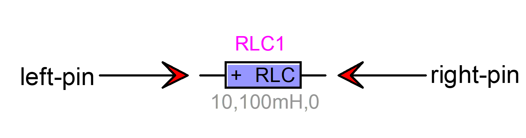
Figure
3
A device with two pins
Pins can be clicked
on to select. There is also a right-click menu.
The design may have
network (circuit) devices: electrical devices or simulated devices recognized
in EMTP®. The libraries in the “Parts by Library” palette allow to select the circuit devices. There
are also various other types of devices. The options.clf library, for example,
has devices for selecting EMTP® simulation options and the
symbols.clf library has several devices for symbol editing.
A Symbol Editor
function invoked through the device right-click menu “Edit Symbol”, can be used
to edit (modify) a device’s symbol (drawing).
Some devices have
color coding options. The voltage source in Figure
2 is shown with a red line to indicate that it
is active in the steady-state solution of EMTP®.
2.1
Device
data
2.1.1
Properties
GUI
Devices have a
right-click menu. In most cases there is also a double-click method. If the
device of Figure
3 is double-clicked the Properties GUI of Figure
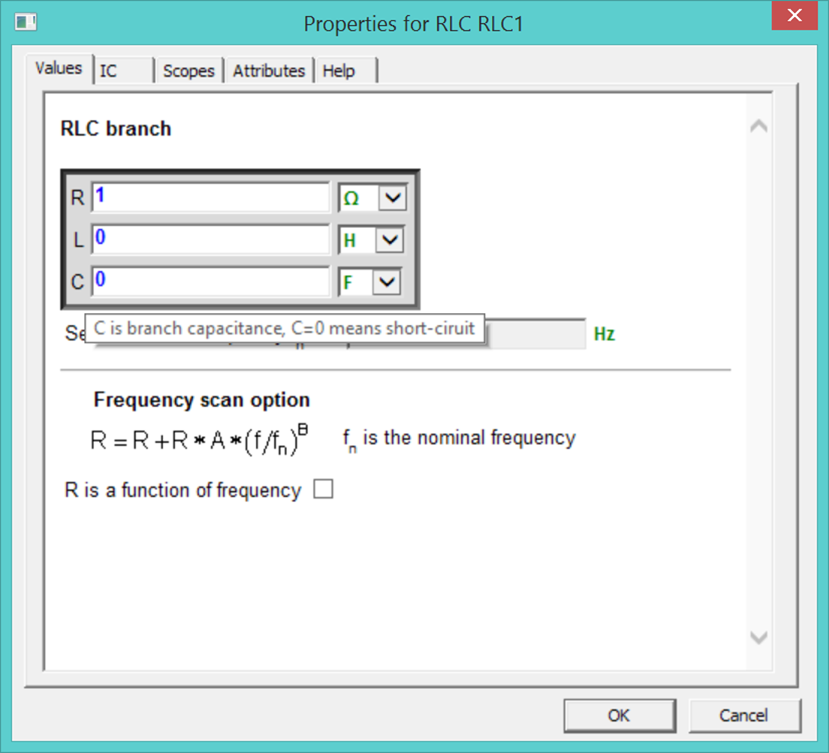
4 appears. This is called the device data web.
The data web is organized using data tabs. Data tabs have data input fields.
The data web is programmed using DHTML. The appearing web can be located on the
user’s computer or anywhere on the internet.
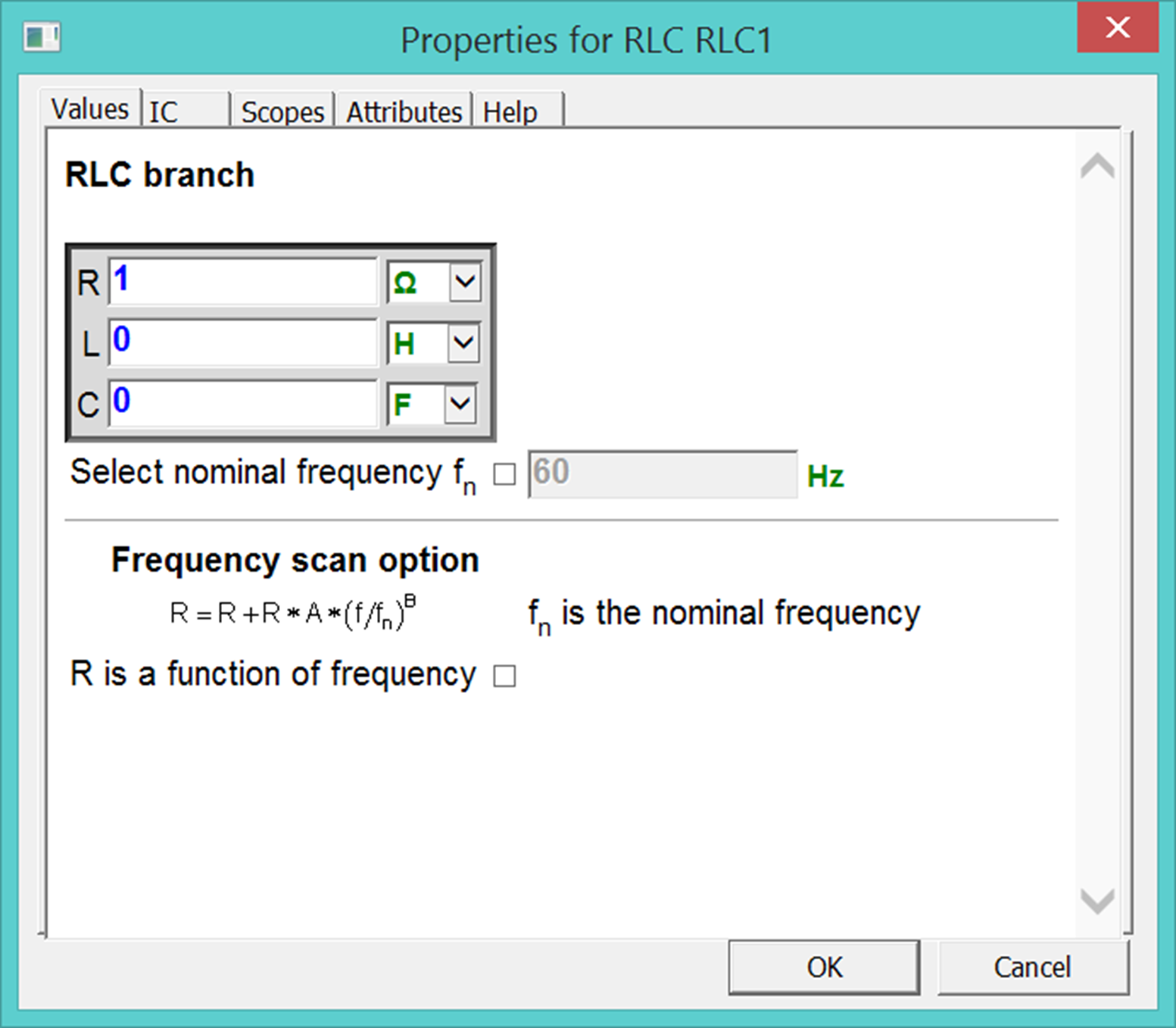
Figure
4
The data tabs of the RLC device
Data entered in data
fields is tested when the user unclicks a field. Data is also tested when
moving between tabs and clicking on the OK button. The blue color is for existing
data. When a data field is unclicked,
the olive color indicates accepted data and the red color signals a corrected
problem. An arbitrary correction is applied in most cases and the user must
verify the faulty field.
The OK button
registers all data changes.
Almost all data
fields have default data. Data errors can revert to default data.
2.1.2
Tooltips
and help
Tooltips and
hyperlinks are provided everywhere in data tabs. To learn about a given device model
parameter (such as R) the user can move the mouse pointer over the parameter’s
name. This is shown in Figure
5. The tooltip panel stays up for an amount of
time fixed by the operating system. The user can continue moving the mouse
pointer to keep the tooltip up indefinitely. For some longer tooltips a
right-click method is available to keep it up until the user clicks anywhere
else into the window. More help is available through hyperlinks and/or in the
Help tab.
Figure
5
The tooltip option
2.1.3
Named values:
simple data field programming
The data fields have
programming options. If the equality sign is the first character in a data
field, it can be followed by a mathematical expression. The JavaScript syntax
is used. An example is shown in Figure
6. The expression is evaluated when the data
field is unclicked.
Another programming
method is the usage of named values (programmed value or variable data). A
named value is a string enclosed between two ‘#’ characters and entered in device
data fields instead of entering numeric values. Example:
#Rfault#
This is a data
programming method. In this version of EMTP®-EMTPWorks it is not
allowed to use named values for devices appearing in the top circuit. More
details on this approach can be found in the documentation of subnetwork
masking methods (see section 5.2).
Usage of named
values is part of the open architecture methods available in EMTPWorks. Entered
data is being determined only after making data substitutions and no testing is
available in data tabs. Usage of such options can result in major data errors
if the user does not follow the data rules and limitations. Only limited
testing is available on EMTP® side for the final device data.
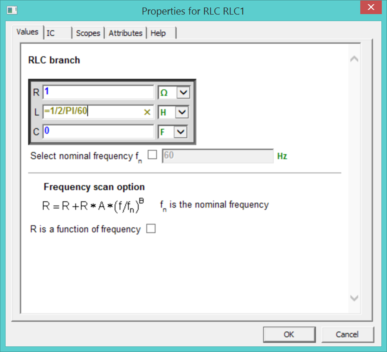
Figure
6
Using the equality sign for simple expressions
2.1.4
Attribute
probe
The Attribute Probe
tool (also called sniffer) can be used to provide quick info on a device. To
activate this option, it is needed to click on the Attribute Probe tool (Home>Tools)
and then single-click on any device. The spacebar deactivates.
2.2
Device
right-click menu
In addition to the
double-click method, each device has a right-click menu (Figure 7) with submenus.
- Copy/Paste: This feature is used to copy and paste device data
(simulation data) between devices of the same type.
- Device Data: This is the same as double-clicking on the device
symbol.
- Extras/Summary: Various options related to the device. For most
devices this menu calls a script for preparing and showing data summary on
the device using its attributes. Some devices do not provide a script for
this menu item.
- Steady-State view: selections for steady-state view options of the
device.
- Exclude/Include: The Exclude action will exclude the selected device
from the Netlist, it will not be seen by EMTP® and will not be
part of the simulation. It becomes an open circuit. Excluded devices have
a grey color code. The Include action will revert to Include back the
device.
- Properties: Shows device info, this is the same as selecting the
device and using CTRL-I.
- Copy name to clipboard: Copies the device name to the clipboard for
a subsequent paste (Ctrl+V) command.
- Attributes: Provides access to device attributes.
- Name: Another method for entering the device name.
- Line Colour: Changes the line color of the device.
- Fill Colour: Changes the fill color of the device.
The remaining
options are self-explanatory.
The “Edit Symbol”
option starts the EMTPWorks symbol editor and allows modifying the device
symbol.
The “Part” menu is
not shown for all devices. It will be used in future versions of EMTPWorks for
part switching from library.
For applying
Exclude/Include actions to several devices selected by clicking while holding
down the SHIFT button or using the mouse bounding box selection method: select
the Design menu “Device Operations>Exclude” or “Device
Operations>Include”.
Other global
functions for both signals and devices are available through the Design menu.
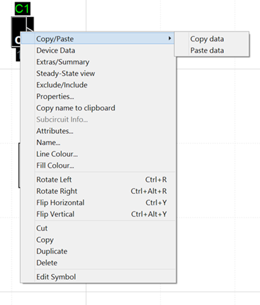
Figure
7
The device right-click menus
2.3
Devices
recognized in EMTP®
A design circuit can
hold various device types. EMTP® can recognize option devices and simulated
devices. There are also model data function devices.
The primitive devices
are recognized in EMTP® using the Part device attribute. The
primitive devices can be of power type or control type. A power type device is
for modeling an actual physical electrical component. A primitive control type
device is a block diagram device. It can be used to simulate actual control
system behavior or for creating electrical network models using function
blocks.
Power type devices
are devices with power pins. Such as the device of Figure
3.
Control type devices
are devices with control pins. Such a device is shown in Figure
8. The control type devices are interfaced with
power type devices using sensors (meters) and actuators.
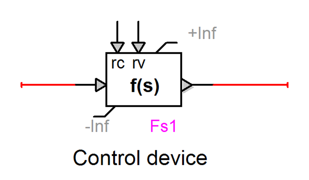
Figure
8
A primitive control type device
A control component
is built in EMTPWorks as a directed graph containing elements joined by
oriented signals, together forming a block-diagram description of the component
to be represented. An example is shown in Figure
9.
Figure
9
Sample control diagram
In a lot of designs
it is preferable to present the control function in a procedural manner. This
can be achieved using the virtual connection method described below. The design
of Figure
10 is functionally identical to the one in Figure
9.
Figure
10
Virtual connection method for procedural assembly of a control diagram
2.4
Device pin
types
There are currently
3 pin types (also called Pin Functions): Power-pin, Input-pin and Output-pin.
The Power-pin is for power devices. A control device may have input pins and/or
output pins.
Signals connected to
control device pins are control signals and do not connect to power pins
directly, meter (sensor) functions are needed. An example of sensor device is
shown in Figure
11. It has a power pin that allows connecting to
a power signal. It also has an output pin that allows connecting into a control
device.
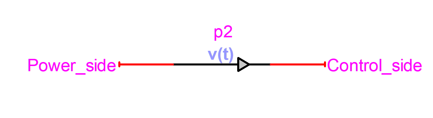
Figure
11
A device with power and output pins: v(t) probe from meters.clf
Some devices may
have control and power pins. This is the case of the controlled thyristor found
in the switches.clf library:
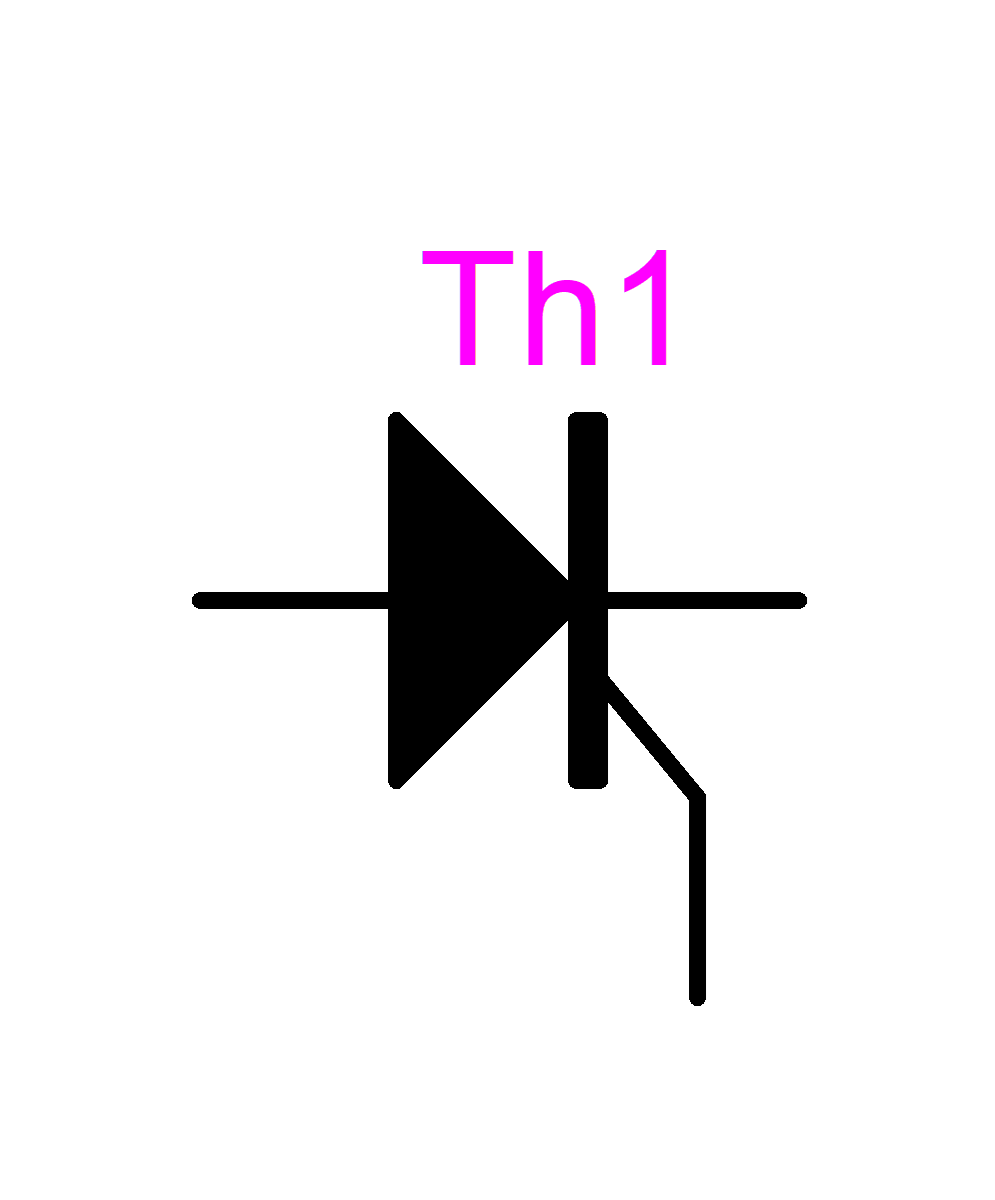
It has two power
pins and one control pin which is for the firing signal.
Subcircuits may have
mixed pin types.
Signals connected to
output pins can only connect to input pins.
Pins that can be
interconnected are called compatible pins.
Device pin settings
are made during the device creation using the Symbol Editor.
2.5
Device
attributes
Device attributes
are used for controlling various device properties. They constitute the
device’s memory and provide behavior rules. The device attributes are
accessible through the right-click device menu. It is only for advanced
usage and programming in the EMTPWorks environment. Erroneous usage can
corrupt device data and create other problems, so extreme caution must be used
when manipulating attribute data.
An example of simple
usage is for altering the default name prefix. If it is desired to change the
name prefix of the RLC device shown in Figure
3:
1
right
click on the device
2
select
Attributes
3
scroll
down to locate the attribute Name.Prefix and select it by single-click
4
change to
“Load”, for example
5
click on
Done
Next time this
device is copied (CTRL-C) or duplicated (CTRL-D) it will change its name prefix
to “Load”.
The device
attributes used for saving EMTP® data into the design and sending
into the Netlist file are:
§ ParamsA
§ ParamsB
§ ParamsC
§ ModelData
All device data webs
are based on scripting using JavaScript with extensions from EMTPWorks and DHTML.
Scripts have access to device attributes for saving data.
Device data formats
are documented in the Help section of each device. Advanced users can apply
programming methods by directly entering device data through its attribute. This
is only for advanced usage.
Other important
device attributes are:
§ Description: used for saving and making visible
device scope requests or initialization options
§ DrawingData: used
for saving device drawing data
§ Exclude: used for excluding a device from the
Netlist
§ FormData: used
for maintaining device data not used in the Netlist of copies of various data
fields
§ Function:
when set to “OPTION” makes
a device for saving and sending simulation options
§ Name: device’s
name
§ Name.Prefix: device’s
name prefix
§ Part: a
unique device identification
§ Script.Info.Dev the
script started from the “Extras/Summary” right-click menu item
§ Script.Open.Dev the
script started when the device is double-clicked
§ Value: for
showing device data in the circuit page
The user can also
add attributes into a design for performing various data manipulations.
Attributes are also part of the template system available in EMTPWorks. A template
file can maintain specific attributes and features for creating design
customization.
A device may have
one or more visible attributes. These are for providing visual feedback for
entered data. The RLC device, for example, shows the R, L and C values in the
Value attribute. The Description attribute is used to show requested device
scopes or indicate manual initialization options. These attributes are
automatically filled by device data scripts.
In the example shown
below the visible Value attribute shows comma separated R, L and C values
respectively. In the Description attribute, “!iv” means that this device has
initial conditions (IC) on both voltage and current. As for “?vip” it gives a
visual indication that this device has voltage, current and power scopes turned
on.
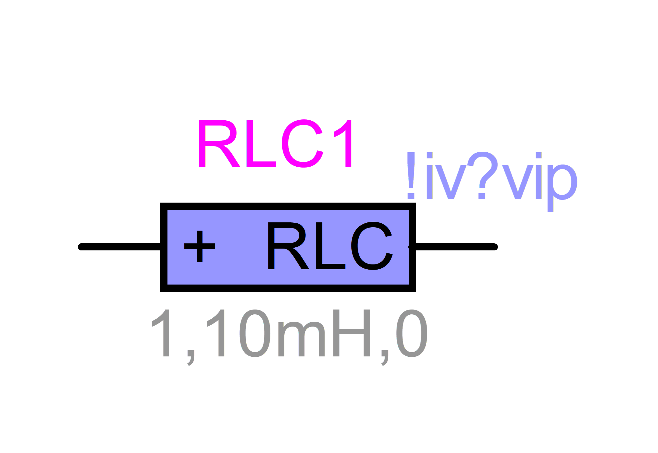
Figure 12 Device with visual attributes for presenting
essential data and identifiers
2.6
Device
libraries
EMTP®-EMTPWorks
built-in devices are available from the built-in libraries. Users can create
other devices and save in new libraries for later usage in other designs.
EMTPWorks has several library options selectable from the “Options>Part
Type” menu. Right-clicking on the library parts list provides library
maintenance options.
3
Signals
3.1
Signal
names
A signal name
must be visible to keep its name. The current version of EMTPWorks has the
freedom to change user given signal names during rerouting if the signal is not
visible. EMTPWorks maintains a
default signal naming system. The default signal naming features are modifiable
through the menus in “Options>Naming Options”.
Signals connected to
control (input or output) pins are control signals. Signals connected to power
pins are power signals.
The currently
reserved power pin signal name is GND. If a signal is named GND then it is
automatically connected to ground (zero-volts). This is only true for power signals.
For control devices
the currently reserved signal name is the number 0. If an input signal
is given the name 0 then it will take the value 0 for the entire simulation.
If an input
signal (connected to an input pin) is not connected to any output signal, EMTP®
assumes that its value is always zero.
Generally speaking it
is not useful and not recommended to name individual signals manually and
to make them visible, unless one needs to create a special reference or apply
connection by name (see description below). Most designs can be carried on without naming
any signal. The power system bus name is on by default, since in this case the
name is a useful reference in the power network diagram.
If it is absolutely
needed to apply virtual connections (connections by name) then a better
approach is to use page connectors. Page connectors can be used on the same
page or on multiple pages (see section 4).
You must clearly
understand the rules and consequences on maintaining signal names before heavy
usage of such methods. The case of signal names in bundles is more complex
and it should be avoided when possible.
3.2
Signal
connectors
EMTPWorks also
provides signal connector devices. A built-in signal connector device is the
“Ground” device:

The “Ground” device
has one pin and its signal name is GND:
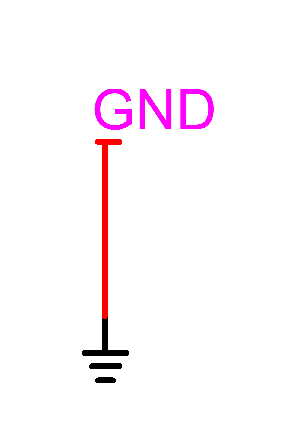
The GND name is an
enforced signal name. It is the pin name of the “Ground” device which is given
the primitive Part type “Signal Connector” in the Symbol Editor. It is illegal
to change the name of such a signal manually.
The user can create
other signal connector devices using the Symbol Editor. This is useful for
making connections by fixing a given signal name through the pin name. In this
example the fixed signal name is SOURCE:

3.3
Connection
methods
The standard method
for interconnecting devices is to draw a signal (click near a pin, hold down
the mouse pointer and move) line between device pins or to connect into an
existing signal from another signal or pin. There are also signal drawing tools
that allow starting anywhere on a circuit page and draw. Figure
13
shows the signal drawing tools from the
EMTPWorks toolbar “Home>Tools”.
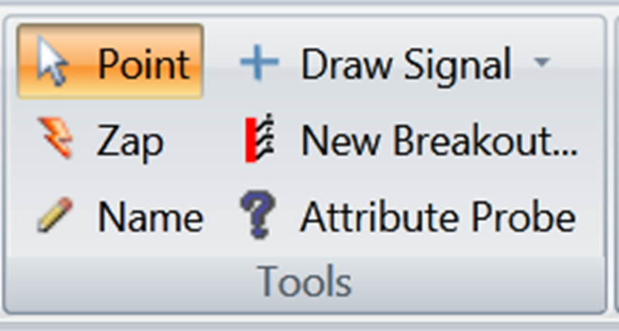
Figure
13
Signal drawing tools
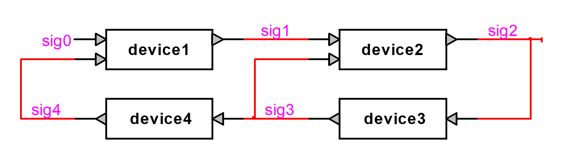
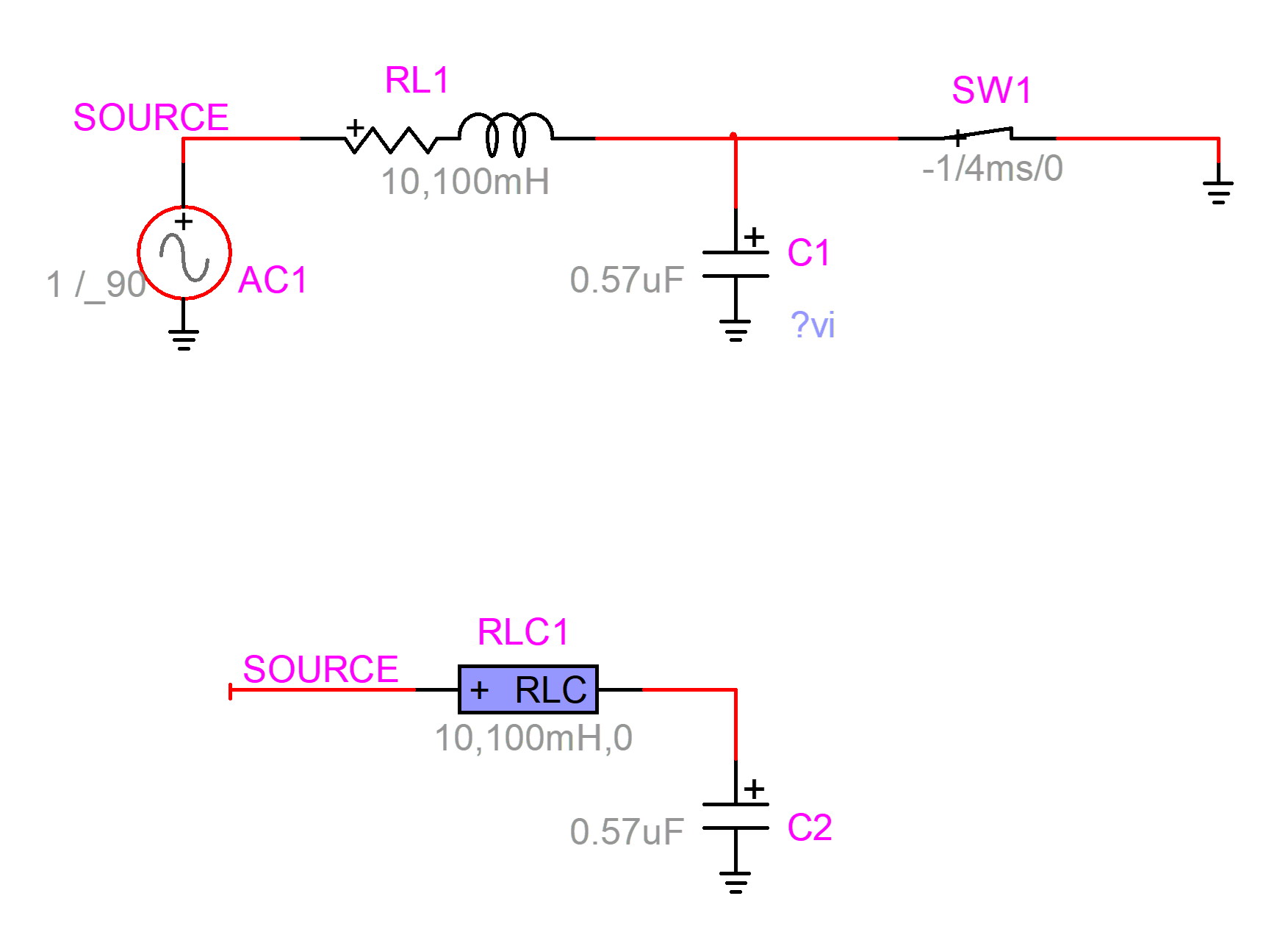
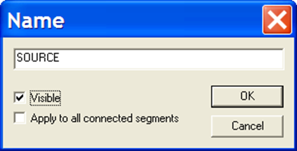
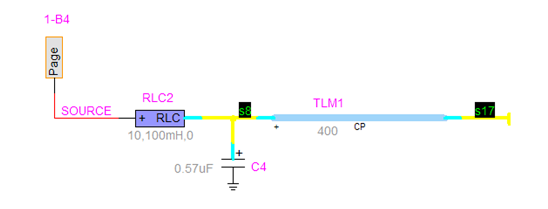
It is also feasible
to connect signals using signal names. This is shown in Figure
14. The signal SOURCE is used to connect the
upper and lower circuit sections in the design without drawing an actual signal
line. This is called a virtual connection or connection by name. The connected
by name signal names must be made visible, or this option will not work. The
name of a signal can be changed through the right-click signal menu item Name.
It is required to check “Apply to all connected segments” to change all virtual
connection names.
Signals connected
by name are not automatically checked for pin compatibility!
The connection by
name method is dangerous and when the user decides to disconnect two or more
signals connected by name, then it is needed to make the signal name invisible
(uncheck visible). In this case EMTPWorks will normally change the hidden name,
but it is recommended to go back, open the name dialog and validate the new
name.
Figure
14
Connecting by signal name
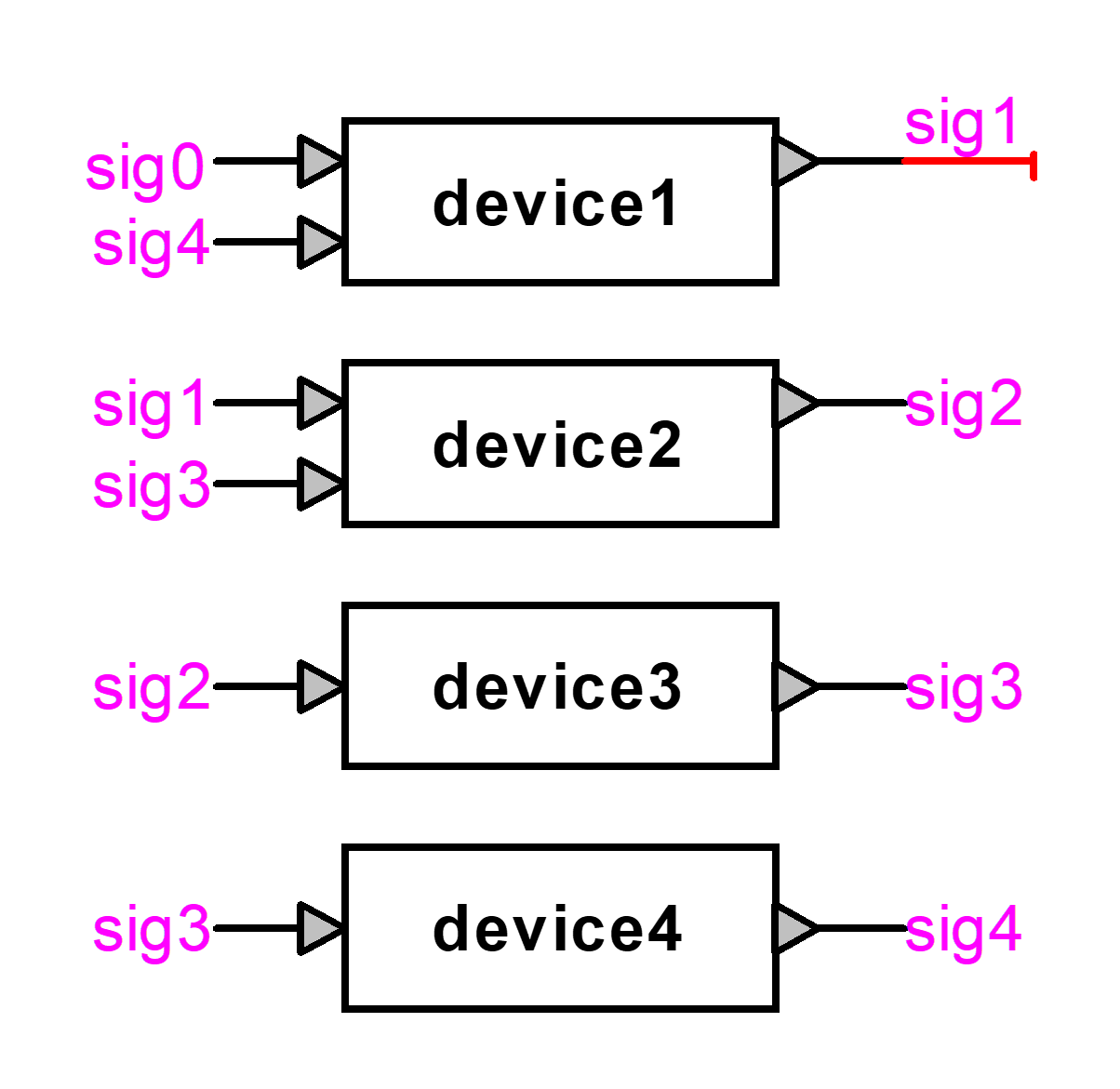
A better approach
when connection by name is absolutely necessary, is to use Page Connectors (also called Inter-Page
Connectors). Page connectors are available in the library “Pseudo Devices.clf”.
It is possible to use them for multipage designs or on the same page. The page
connector approach is shown in Figure
15. Connection is created by naming the page
connector instead of the attached signal.
This approach is
more robust and provides visual location feedback (automatic display of page
references) on the locations of connected signals. In this case it indicates
that 1-B3 (coordinates using design sheet border numbers) the connected signal
is found on page 1 at the geographical location B3. The same applies to all
pages connectors. The connection is created using the same name for the two
page connectors. Two or more page connectors can be used. Page connectors can
appear on the same page or on different pages when using multipage designs (see
section 4).
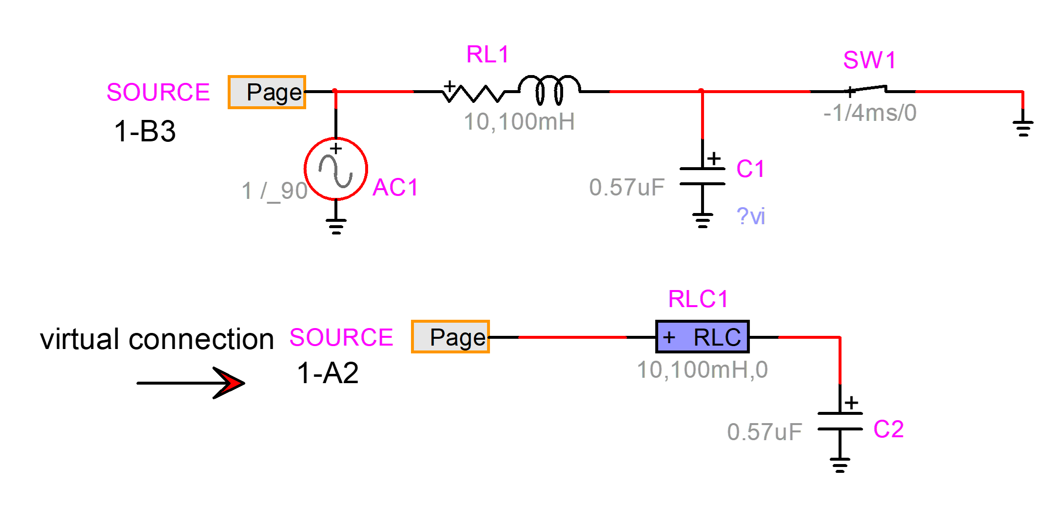
Figure 15 Creating a virtual connection using Page Connectors
To turn on the
visual location feedback it is needed to go to the menu “Options>Design
Preferences” and select the “Page Refs” tab. In this tab the checkbox “Enable
Automatic Page References” must be checked. This is shown in the figure below.
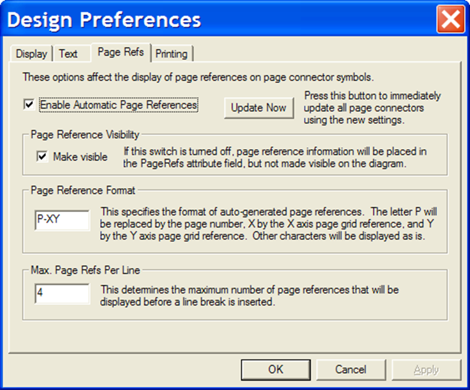
Figure 16 Design Preferences for setting up page references used in Page Connector devices
The library “Pseudo
Devices.clf” contains other types of page connectors.
In addition to
connecting by drawing a signal, a device can be connected to a signal by moving
the device near the signal and touching the signal with its compatible pin.
This is called connect-by-proximity. Under some circumstances when entire
circuit sections or devices are moved near or over other circuit sections, the
connect-by-proximity can become a nuisance, and can be turned-off by holding
down the CTRL key after starting the move.
3.4
Showing
and selecting connectivity
A single-click on a
signal, highlights the signal and shows its connectivity. A double-click on a
signal shows virtual connectivity. A single-click on a signal name highlights
its parent signal.
Holding the CTRL
button and double-clicking on a device selects the entire interconnected
circuit, but not the virtually connected circuit. The selected circuit can be
moved around using the mouse pointer (hold down any device and move) or use the
keyboard arrow keys.
3.5
Signal
paths
The signal path can
be modified and only parts of a signal can be deleted using the Zap tool. The
user can also experiment with:
12.
hold SHIFT
and draw
13.
hold CTRL
and draw
14.
hold ALT
and draw
15.
hold
CTRL-ALT and draw
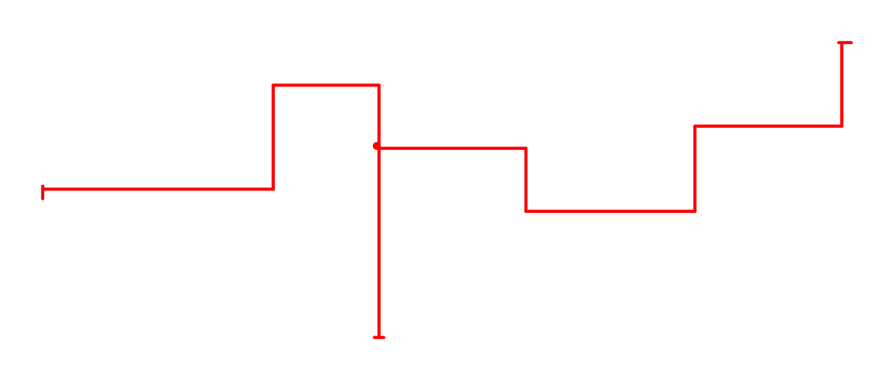
Figure 17 Signal paths
The tip of a signal
which is not physically connected is a T-shape.
The “View>Redraw”
or End button can be used to refresh the design drawing.
3.6
Signal
Line Type
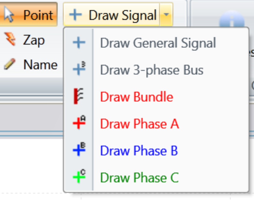
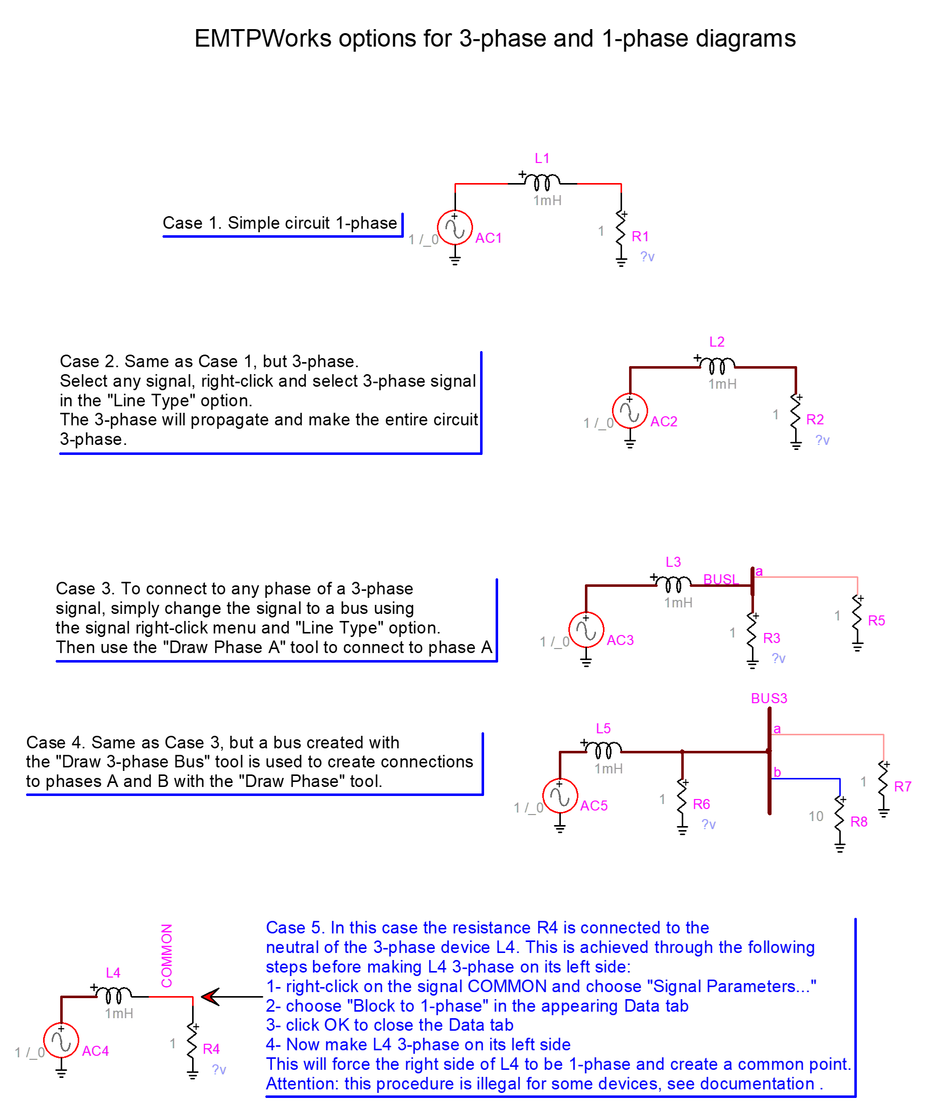
The default signal
is called a general signal. It is a 1-phase signal. It can be drawn by starting
from an existing signal or device pin or by using the “Draw signal tool” shown
as the first tool button in Figure
13.
A control signal can
only be a general signal. A power signal can be a: 3-Phase Signal, 3-Phase Bus,
Phase A signal, Phase B signal or Phase C signal.
The signal Line Type
is selectable through the signal right-click menu item “Line Type”. If any of
the signals shown in Figure
2 is right-clicked and set to become a “3-Phase
Signal” then EMTPWorks propagates the phase setting to the entire circuit (see Figure
18).
Figure
18
The 3-phase version of the circuit shown in Figure
2
A 3-phase signal
internally carries 3 names, one for each phase. For the signal SOURCE shown in Figure
18, the internal names are SOURCEa, SOURCEb and
SOURCEc. The same is done for device names. A 3-phase device can be decoupled
or internally coupled.
It is allowed to
move back to the 1-phase version of a signal, again using the signal “Line
Type” option.
The signal
propagation may give an error message if at least one device in the circuit
does not accept 3-phase signals. The user can go back by selecting Undo
(CTRL+Z), the 1-phase devices will become otherwise disconnected in the Netlist
and errors may occur.
Some device pins can
only be 1-phase (general signal). This the case of a diode model, for example,
which exists only as a 1-phase device.
Some device pins can
only be 3-phase. This is the case of a 3-phase machine, for example.
The signal drawn
from a pin takes its phase property. The user can also create separate signals
using the signal drawing tools shown in Figure
13. The second option in this figure is the “Draw
3-phase Bus” tool. A 3-phase bus can only connect to 3-phase signals. It is
also allowed connecting to individual phases, as shown in Figure
19.
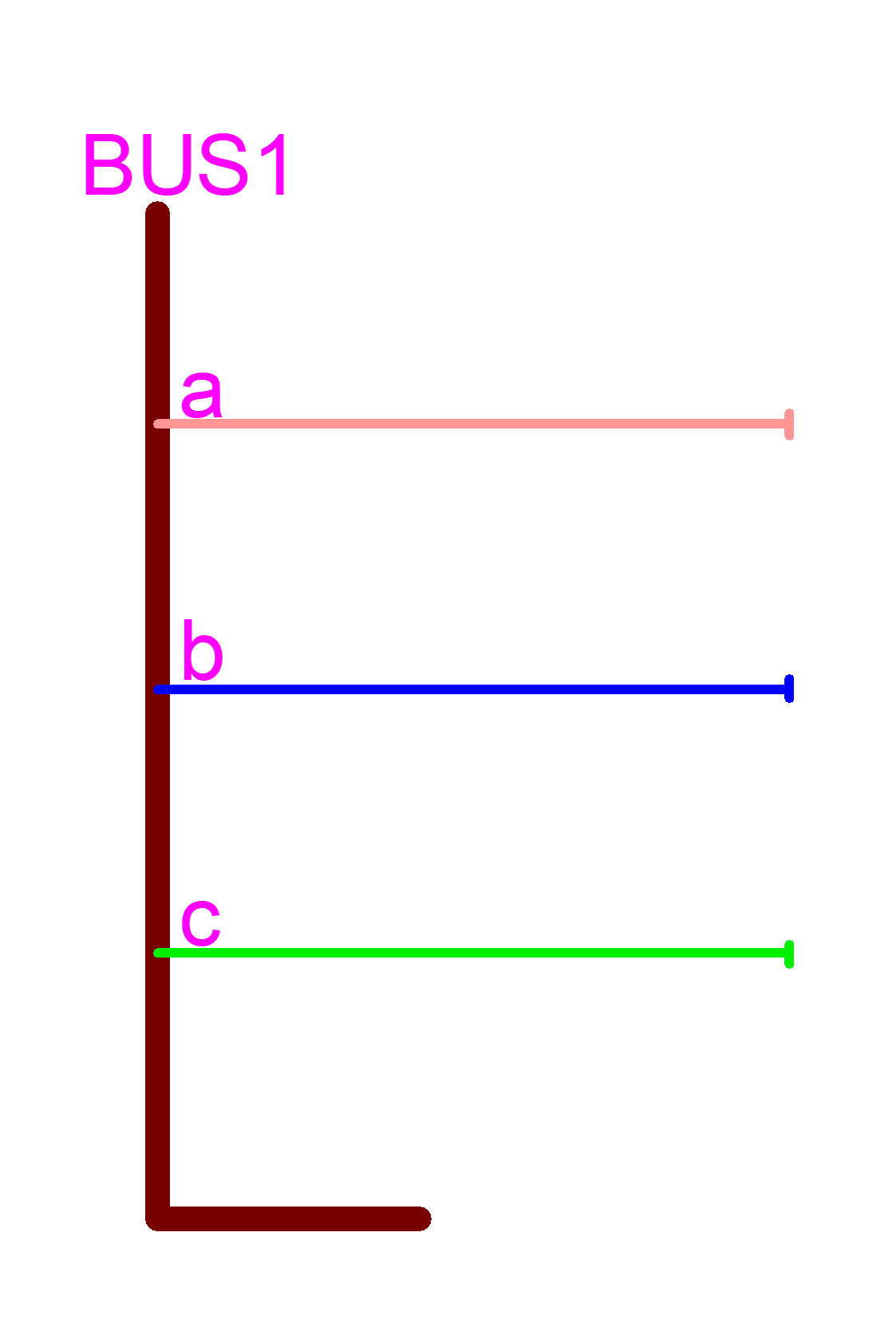
Figure
19
3-phase bus with color code phase signals
Phase signals are
drawn using the phase signal buttons shown in Figure
13. Phase signals are also created by converting
a 3-phase signal line type to “Phase A” (or B or C) type.
The 3-phase bus acts
as a signal concentrator, it has only one name, but appends the phase character
to each phase signal, such BUS1a, BUS1b and BUS1c. If a phase name is changed
then the parent bus name is also changed.
Naming a phase
signal or bus GND will ground all phase signals. The ground signal GND is not replicated using
phase characters.
It is not allowed to
connect phase signals of a given 3-phase bus together directly. In Figure
19, for example, phase a will not connect to
phase b. There are two options for achieving such connections. The first option
is to use an ideal closed switch device. The second option is to use a node
shorter (“Node connector”) device created using subcircuits. A similar approach
can be used for connecting the 3-phase signal or any phase signals to ground.
Several types of node connector devices are available in the library “Pseudo
Devices.clf”.
If a phase signal is
drawn separately in a design using the “Draw Phase” tool, then its name is
internally concatenated with the phase character. In this example:
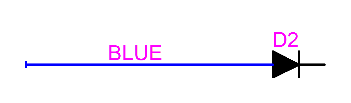
the actual signal
name is BLUEb.
More details on
3-phase and 1-phase signals are given in Figure
20. This design is available in the example three_and_one_phase_diagrams.ecf
under the EMTPWorks directory Examples\ShowHow.
3.7
The bundle
The bundle is a
special signal that allows gathering and sending several signals through a
single channel (or signal bus). It can also act as a multiplexer. The bundle is
also used to interconnect device bundle pins. It is a visual concentration of
signals.
The bundle uses
bundle pins. Signals are connected to bundle pins. Bundle pins are added using
the bundle right-click Breakout menu or the keyboard shortcut CTRL-B (Edit
Breakout function).
Transmitting through
a bundle can become complex and mixed signal types may remain undetected. This
feature must be used with caution.
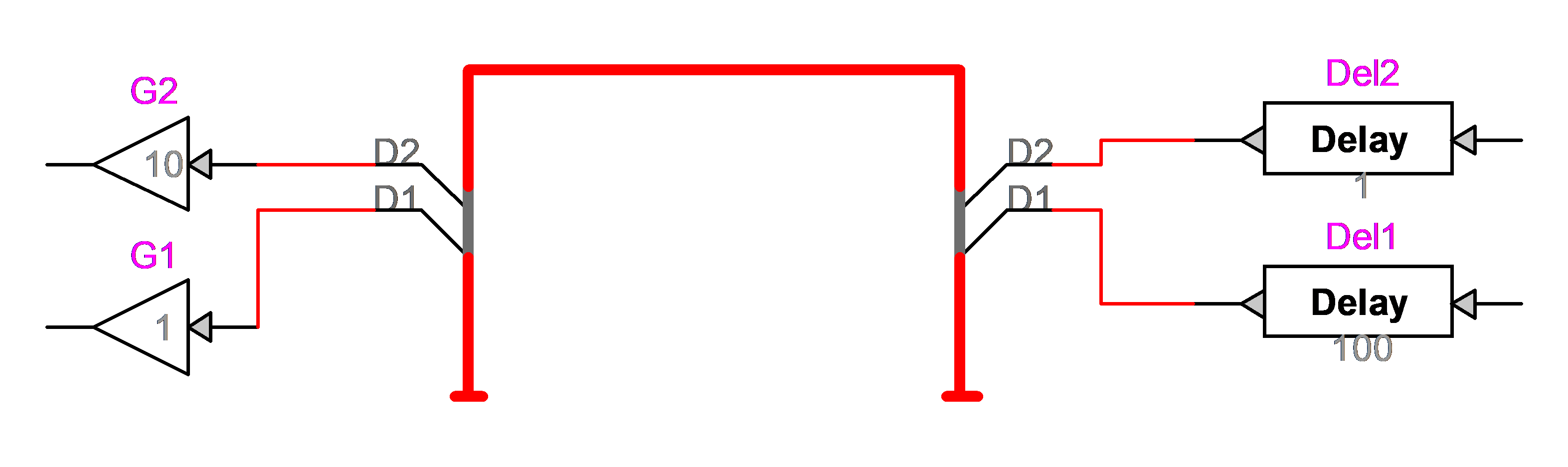
Bundles are drawn
using the “Draw Bundle” tool (Draw Signal menu, Home ribbon) from Figure
13. An example is shown in Figure
21. It is important to remember that signals
going through a bundle have the bundle name as a prefix. In Figure
21, D1 is actually BUND_D1.
The bundle pin name
forces the name of the connecting signal. The signal inherits the bundle pin
name when it connects to the pin. The bundle pin signal name is always prefixed
by its bundle name.
The right-click
command on the bundle of Figure
21 opens the “Edit Breakout” menu shown below.
This menu is also accessible through the command “New Breakout” shown in Figure
13. New pins can be entered or selected from this
menu. Any number of pins can be selected for establishing connections anywhere
on the bundle path. In Figure
21 the breakout pins on the right are created and
those on the right are selected.
Changing a bundle
pin name manually (double-click on the name and change) will not change the
name of the corresponding signal, but will add a new pin in the bundle. In this
example changing the name of D1 on the left to NewD actually creates a new pin
and abandons the previous connection to D1. The “New Breakout” menu now shows 3
pins (see figure below). This is the case when the bundle pin has been already
used as in Figure
21.
Bundle pins can be
of type Power-pin, Input-pin or Output-pin. All signal line types are accepted.
A pin created using the “New Breakout” has no initial type and inherits its
type from the signal connected at a later stage.
As for the case of
3-phase signals, it is not allowed to connect bundle signals together. It is
however feasible to use ideal switches as jumpers or to use specific shorting
devices (“Node connector” or “Control signal connector” devices are found in
the library “Pseudo Devices”).
It is also possible
to connect directly into bundles by drawing a signal into the bundle. This
method shown in Figure 24. When a signal is directly connected to a
bundle, a connection menu (Bundle Connection) appears and allows to specify the
connection with signals in the bundle.
When two bundles are
connected together, it is necessary to specify the connections between existing
signals. This is also performed using Bundle Connection menu that appears
automatically when a connection is maded.
Figure
20
EMTPWorks options for 3-phase and 1-phase diagrams
Figure
21
Bundle usage example
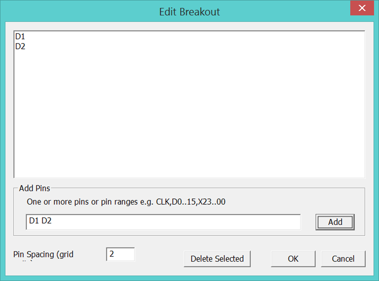
Figure 22 “New Breakout” menu
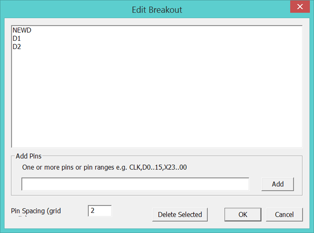
Figure 23 “New Breakout” menu after changing the name of
a pin
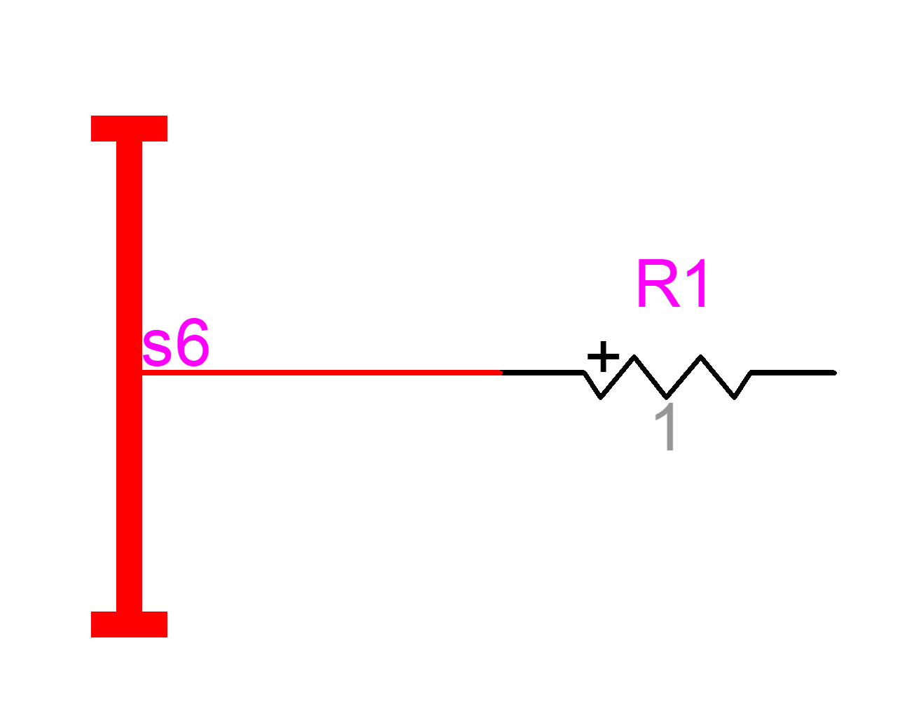
Figure 24 Connecting directing into a bundle without breakout usage
4
Multipage
designs
An EMTPWorks design
can have one or more pages.
Steps for adding
pages and using page connectors:
1
right-click
in the circuit and select the “Pages” menu.
2
give a
name to the current page
3
click on
“New Page”
4
give a
name to the new page
When circuits appearing
on one or more pages are interconnected, it is needed to use the same signal
names (virtual connections). Before placing page connectors, it is useful to
select “Options>Design Preferences” and then “Page Refs”. In the “Page Refs”
panel all the checkboxes must be on (see Figure
16).
Page connectors are
available in the “Pseudo Devices.clf” library. It is needed to select a “Page
Conn Power Signal” for adding page connectors to power signals. If the signal
SOURCE is used to connect pages then the circuit pages will give the page
connectors shown in Figure
25. The first character is the page number and
the following two characters give the geographical position in the page. A
right-click selection of “Properties” of a page connector shows all related
page connections and allows to jump between page connectors.
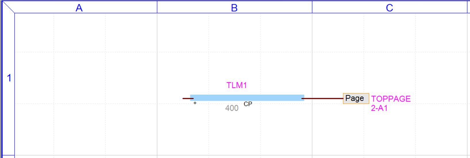
a)
Page 1
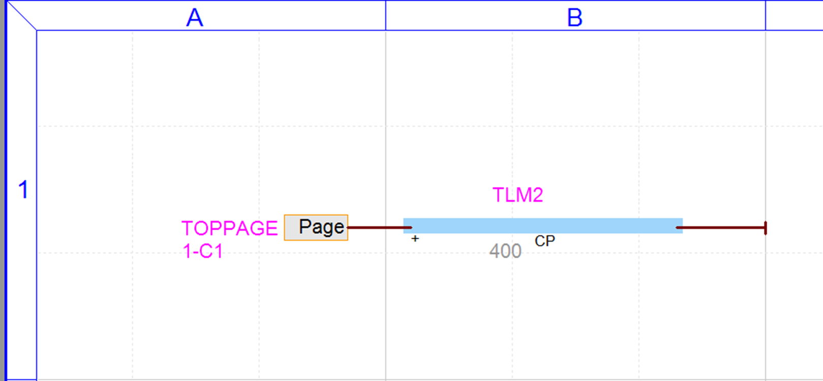
b)
Page 2
Figure
25
Page connector usage
5
Subnetworks
(Subcircuits)
Subcircuits are an
important design feature. They are used to simplify drawings, to provide
encapsulation and to create modules. Another important feature available
through subcircuits is masking and user-defined modeling.
EMTPWorks offers
several methods for creating subcircuits. Subcircuits can be created from any
location in a circuit. It is also possible to make a subcircuit from the entire
circuit.
The subcircuit of Figure
26 is created from the switch of Figure
2. The “Options>Subcircuit>Create
Subcircuit Block” (CTRL+SHIFT+Q) menu is used to create a subcircuit from parts
of a circuit. If port connectors are not placed before using CTRL+SHIFT+Q, then EMTPWorks suggests
automatic port positions, such as “Add port connectors to all signals with
visible names” or “Add port connectors to all signals with loose ends”.
A subcircuit may
have zero, one or more pins. Any pin types can be used.
The top circuit can
contain several subcircuits and each subcircuit can also contain subcircuits
with unlimited number of levels.
The default
subcircuit symbol is a square box. The Symbol Editor can be used to modify the
subcircuit symbol.
After creating the
subcircuit it can be opened in a separate circuit drawing by double-clicking on
its symbol. The available keyboard shortcuts are: “CTRL+SHIFT+I” (in) for
getting into the subcircuit and “CTRL+SHIFT+U” (up) for going up.
The first time a
subcircuit is entered it is locked. It is needed to unlock the subcircuit for making changes. There are
two methods for unlocking: through the “Circuit
Info” menu (CTRL+I) or by moving a device in the subcircuit and
accepting to unlock from the subsequent panel popup.
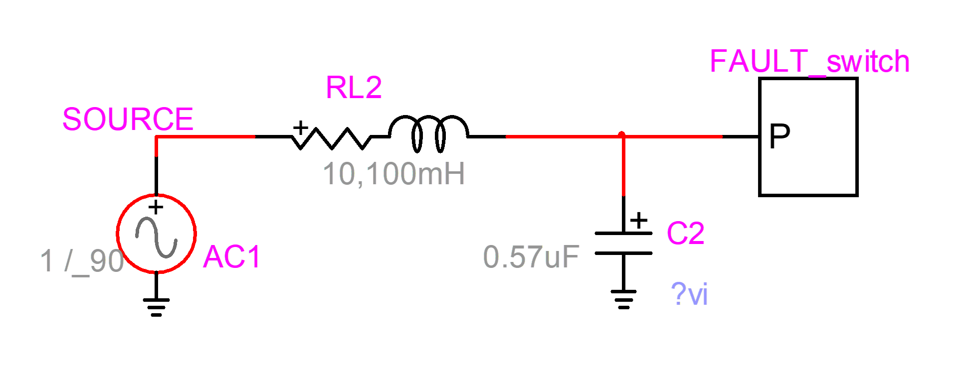
Figure
26
Subcircuit FAULT_switch created from the circuit of Figure
2
The contents of
FAULT_switch are shown in Figure
27. The square with an X is a device used for pin
interface location with the parent circuit.

Figure 27
Subcircuit FAULT_switch
5.1
Subcircuit
uniqueness
A fundamental
feature that must be clearly understood before using subnetworks (subcricuits)
is explained below.
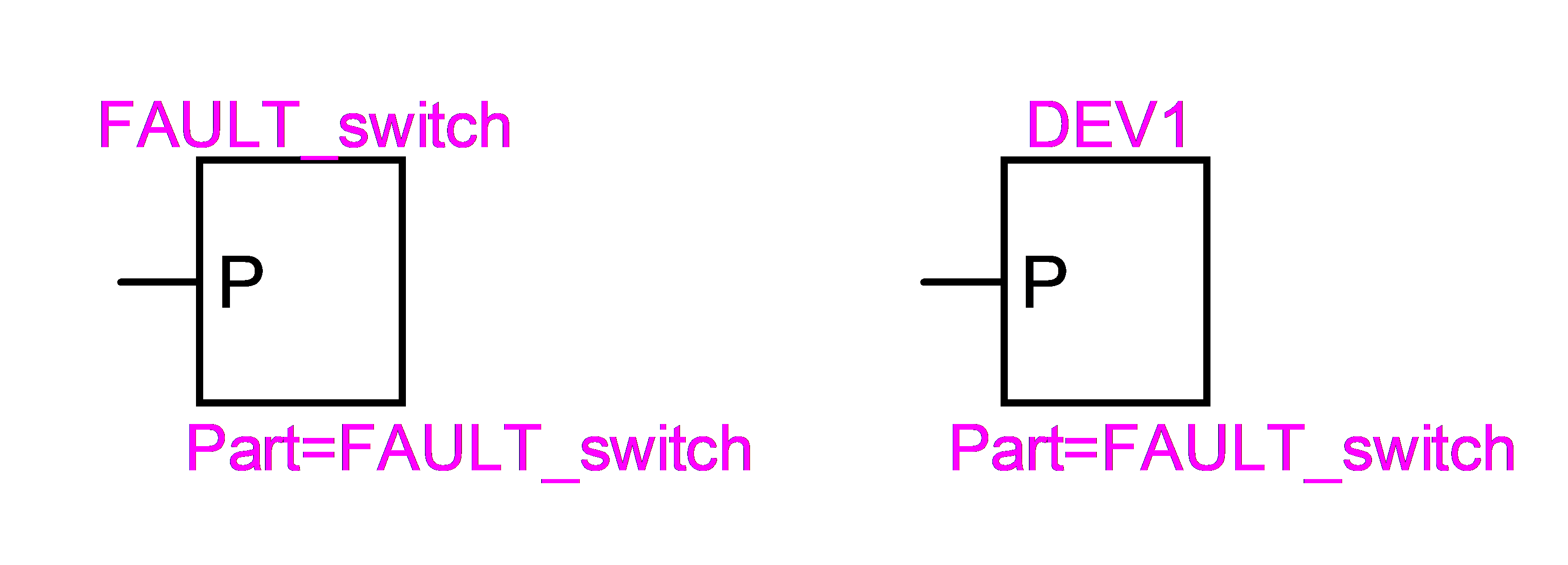
When a subcircuit is
created and duplicated, EMTPWorks continues keeping only one copy of its
internal circuit. Which means that any
changes inside one subcircuit are automatically reflected into the
other subcircuit instance. EMTP® also sees only one copy of the
circuit, but two separate calls. This is similar to programming using a given
function from different locations in the program. The two subcircuits of Figure
28 are identical. They have the same Part
attribute and same Type name. This is a powerful feature for large designs. If
a large number of subcircuit devices of the same type are used in a design,
then by changing only one device allows changing all other devices
automatically.
Figure
28
Identical subcircuits
The Type name of a
device can be found by selecting the device and using the right-click
Properties command.
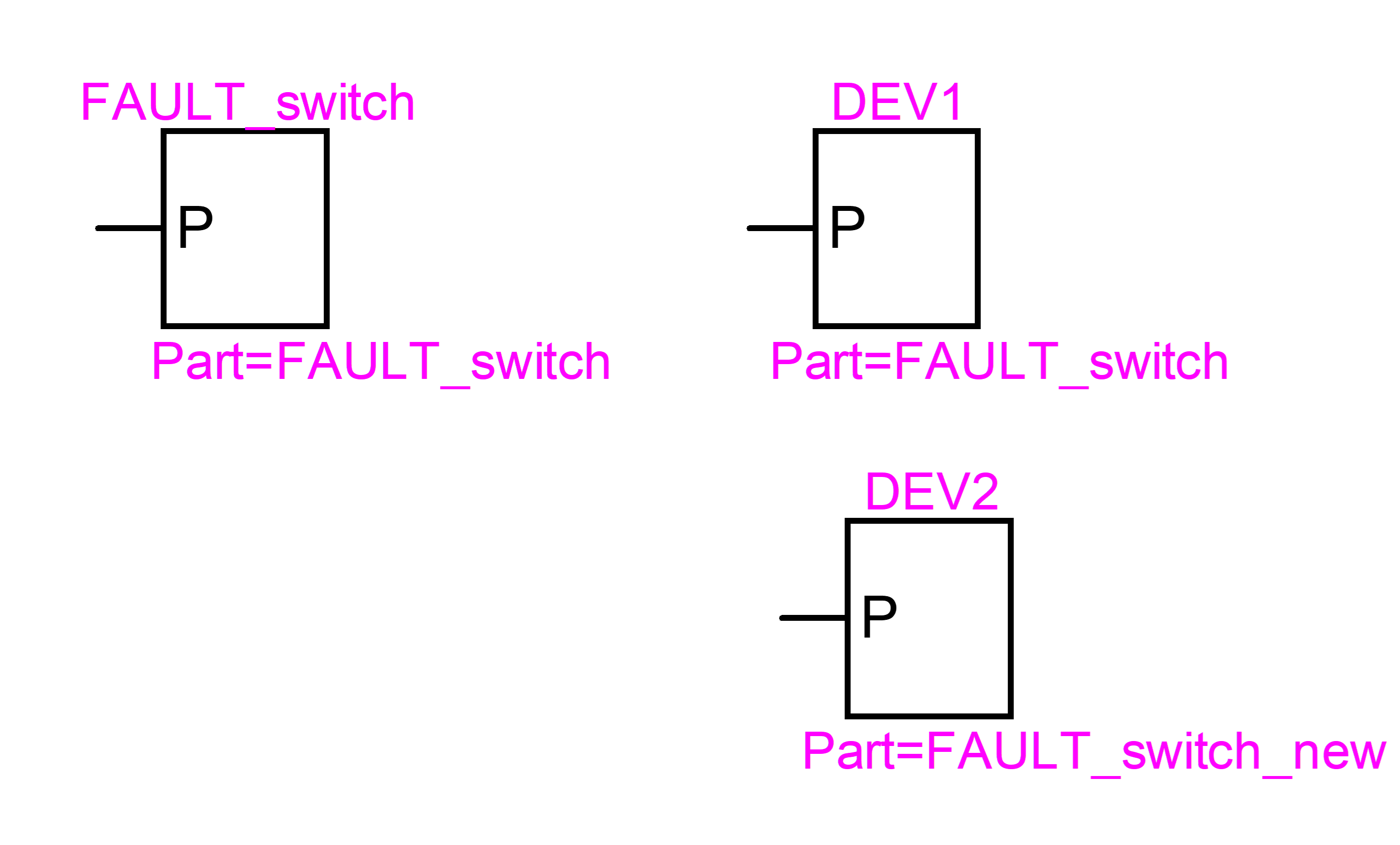
If it desired to
detach one subcircuit definition from the other, then the detached subcircuit
must be made unique. This is completed through the “Options>Part
Type>Make Unique Type” menu. In Figure
29, the subcircuit DEV2 is first created by
duplicating DEV1 and then made unique. To ensure circuit data integrity and to
manage subcircuits, it is very important to enable visual feedback for
distinguishing dissimilar subcircuits. A suggested approach is to show the Part
name assuming that the user is maintaining appropriate Part names. An even
better approach is to change the subcircuit symbol using the Symbol Editor.
It is very important
to understand the implications of the “Make Unique Type” command and the notion
of subcircuit uniqueness before making any changes to subcircuits. The user
should never modify a built-in EMTPWorks subcircuit based device before
applying the “Make Unique Type” command to the device. A built-in device may be
used by other devices and thus modify their contents if not made unique before
changing. More details can be found by looking into the “Make Unique Type”
index in “File>Help&Support>Help Documentation>Using EMTP
-Tutorials and Reference”
EMTPWorks also keeps
a separate attribute PartTemp for verifying uniqueness when the user makes
mistakes by using existing part names or makes attribute changes without making
a unique type.
Figure
29
Making a subcircuit unique
At this stage DEV2
is detached from DEV1 and FAULT_switch: it has its own copy of the original
subcircuit. This is similar to making a copy of a function and renaming it to
allow new contents, calling methods and usage.
If a subcircuit is
available in a library and if it is dragged into the design and modified, then
it becomes automatically unique: detached from the library copy. The user
should change the symbol and make the new Part name visible to avoid confusion.
Any new copy dragged in from the original library remains detached from the
one modified in the design.
Locking the contents
of a subcircuit after its creation is used for reminding the user about the potential
repercussions of changes made in the subcircuit.
The contents of a
subcircuit are only visible from the subcircuit. This means that two devices with the same
name but in two different subcircuits do not actually have the same internal
name. The same is true for internal signals, but not for interfacing signals.
An interfacing signal is a signal connected to a subcircuit pin. Such a signal
will keep its name when propagating downwards from parent circuit or subcircuit
into lower level subcircuits.
It is allowed to add
and delete subnetwork pins after subnetwork creation. When a signal line type
is changed in a subnetwork after its creation, it will not propagate to its
parent circuit. Such changes must be performed manually. Changing signal line
types in the parent circuit must be also achieved by changing the subnetwork
pin types manually.
In the current
version of EMTPWorks, subcircuit control input and output pins are not
automatically given an arrow tip. This is only achievable by modifying the
subcircuit symbol using the Symbol Editor.
If after exiting a
subcircuit, the user receives an error message, it means that there is pin
interface corruption in the subcircuit and the resulting Netlist will also have
problems. Error and warning messages should not be ignored before continuing.
5.2
Subcircuit
masking
After creating the
subcircuit the right-click device menu item “Subcricuit Info” becomes enabled.
The “Subcircuit Properties” has a mask tab with a default mask.
Masking is a
powerful feature for data hiding and encapsulation. It provides a high-level
access to subcircuit contents and allows creating user defined models.
Help on masking
methods is available after selecting this option and looking into the Help tab
of the default mask.
5.3
Subcircuit
contents
Subcircuits can
contain subcircuits which can also contain subcircuits. This is called
hierarchical design.
Subcircuits can have
any number of pins. The pin names are used for connecting signals to subcircuit
contents. It is also allowed to create subcircuits without pins. Subcircuits
can contain devices explicitly recognized by EMTP®, generic symbols
or drawing annotations.
When a signal is
entering a subcircuit pin, its name is automatically propagated downwards into
subcircuit contents. The subcircuit contents are only visible at its circuit
level. The subcircuit has its own data scope. Each subcircuit has its own
pathname. The device named SW1 in the Fault_switch subcircuit of Figure
26 is referred to as Fault_switch/SW1. If
Fault_switch contained another subcircuit, named Inside, for example, then it
would be also referred to as Fault_switch/Inside.
As long as the pin
interface with subcircuit contents is correctly setup, there are no limitations
in the internal subcircuit connectivity rules. In the example of Figure
30, a dummy device is created for shorting
signals (nodes) together. Such a device can be used, for example, when it is
not allowed to connect given signals together directly. It is used in Figure
31 (black square) for shorting BUS12a and BUS12b
phases. Such a connection is not allowed otherwise.

Figure 30
Subcircuit for shorting signals: Node connecter
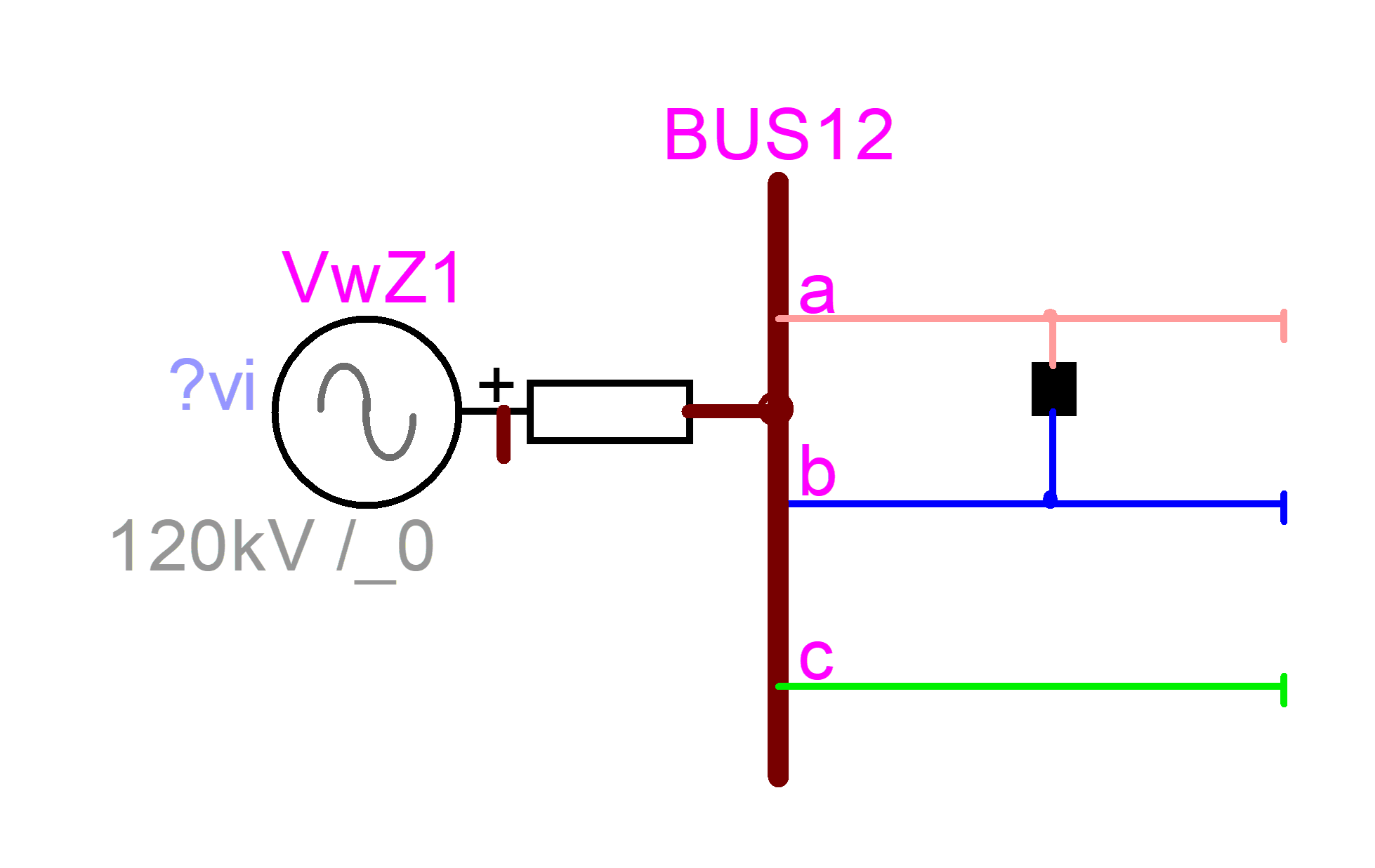
Figure 31
Shorting phase signals using a “Node connecter”
5.4
Subcircuits
within subcircuits
As understood in the
previous section, a subcircuit may contain other subcircuits and the contained
subcircuits may contain subcircuits, which results into a tree of subcircuits.
The best way to
understand multilevel designs and Unique property of a subcircuit, is to view a
subcircuit as a program function. A function is a program building block. A
given function has only one version and can be called from other functions. If
it is desired to change a function, then its name must be changed (made unique)
in order to change its contents. A subcircuit level can be viewed as the body
of the function.
The best way to
illustrate this concept is to create a simple example.
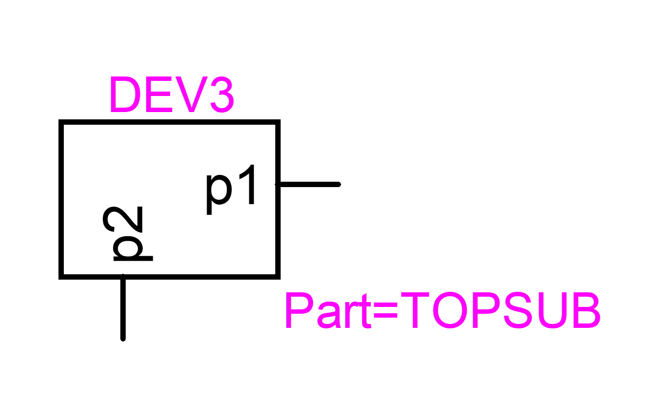
Two subcircuits FUN1
and FUN2 are contained in a subcircuit TOPSUB.
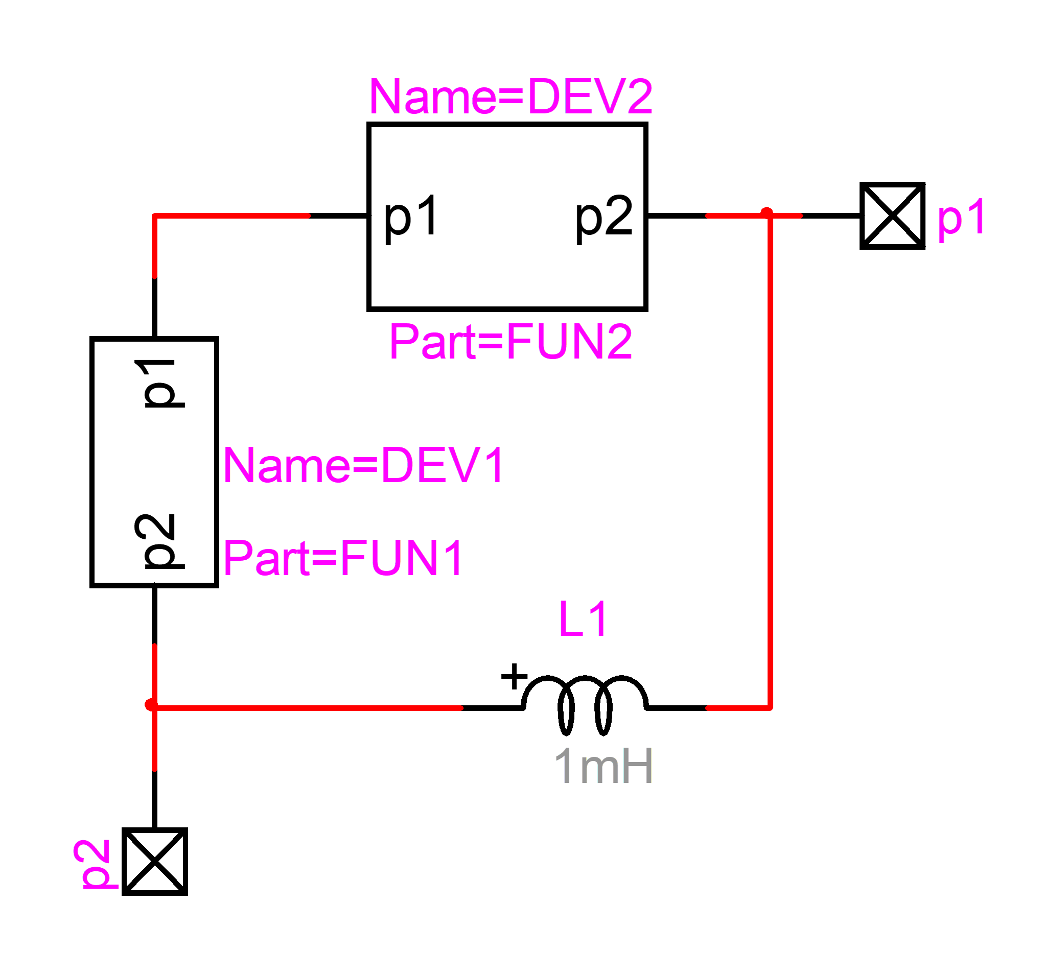
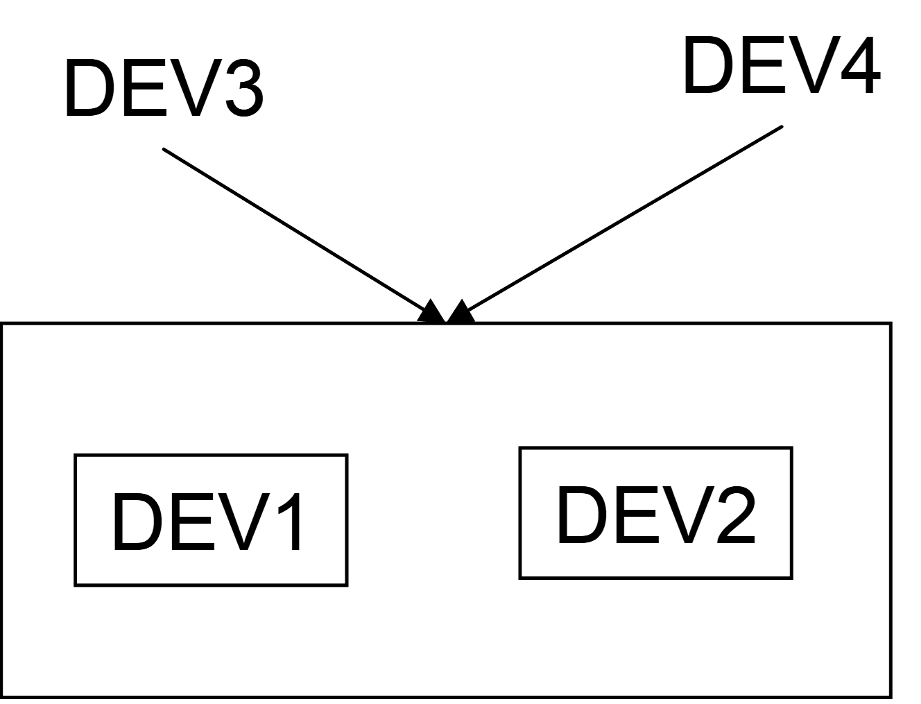
Initially there is
only one copy of TOPSUB in the memory. There is also only one copy of FUN1 and
one copy of FUN2. Making any changes in the TOPSUB level is automatically
reflected into all copies of TOPSUB. The same is true for FUN1 and FUN2.
If we make a copy of
TOPSUB to create DEV4 it is like calling the same function tree from another
location in the main program (the top circuit).

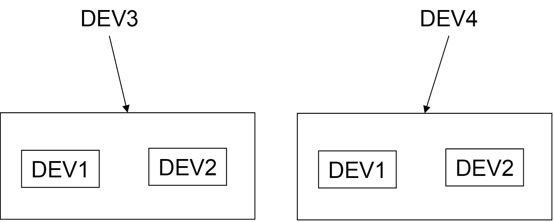
Making any changes
in the DEV4 level is automatically reflected into DEV3 level. If it is desired
to modify FUN2 in DEV3 without modifying FUN2 in DEV4, DEV3 must be first
converted to become unique using the Make Unique Type procedure. Its level
will then become separated in memory from DEV4. Then DEV2 can be also set to a
new type using again Make Unique Type. This last action will detach DEV2
and allow modifying its level contents. Here is a visual representation of the
steps. First DEV3 and DEV4 are sharing the same body:
Then DEV3 becomes
unique, holds its own body, but continues sharing DEV1 and DEV2:
The next step
detaches DEV2 by making it unique.
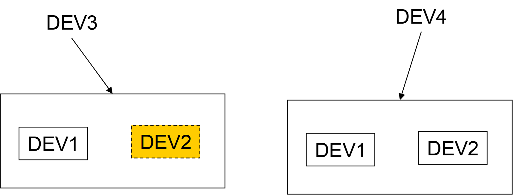
This means that if
you want to modify a multilevel subcircuit to make it completely detached from
others in all its levels and used subcircuits, you must modify all hierarchical
levels.
It is also feasible
to propagate uniqueness from top down for a subcircuit device containing other
subcircuits by checking the option “Apply to subcircuit contents” on the Make
Unique Type command panel.
One exception to the
explanation above is when a subcircuit contained within a subcircuit is also
available at the top level design (not in a subcircuit). In this case it is
possible to create two separate definitions by making one of the subcircuits
unique.
6
Search
options
Search options are
available from “Home>Find” or CTRL-F shortcut as shown in Figure 32.
The “Quick Find”
method can be used by searching for devices and signals. The object name must
entered into the indicated field. This function will also look at any name
string and search for entered characters.
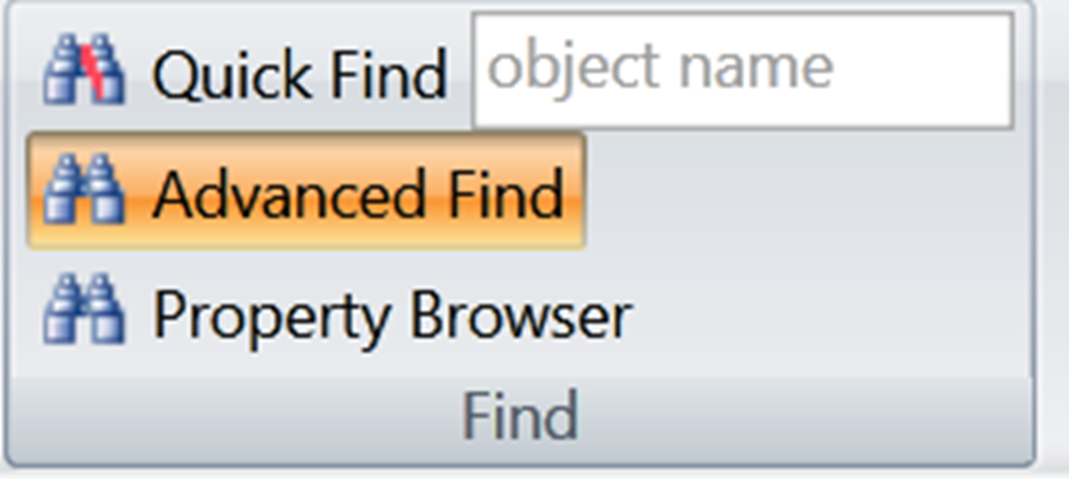
Figure 32 Search options
The Advanced Find
method opens a tab on the right hand side and allows to select options. There
are currently 4 options.
“EMTP Error Check”
is the first option. It can be used to detect potential problems and verify
error messages. Some warning messages can be inconsequential. The most common
sources of errors are devices with incomplete data. Other important messages
are related to mixed signal types.
“Find Devices by
Name” allows searching for devices in the entire design (all circuit levels).
“Find Devices by
Name (cc)” allows searching for devices in the current circuit level.
“Find Signals by
Name” is for searching for signals in the current circuit level.
7
Copying
and pasting
Entire circuits or
circuit parts can be copied within the same design or into other designs. Due
to the signal naming methods explained before, the user must be careful not to
create virtual connections or duplicate device names at the same circuit level.
Pasting options are
selectable from the “Home>Clipboard>Paste Special” menu.
To copy circuits
into other applications is achieved by simply selecting the desired circuit
section and pasting. Best quality is achieved by copying at the highest zoom
level in EMTPWorks drawing pages.
If a circuit
contains text annotations, then it is required to select a paste-special option
in the target application and specify “Picture (Enhanced Metafile)”.
It is also allowed
to copy into a circuit page from other applications. A useful application is
the copying of mathematical equations or other text annotations from separate
tools.
8
Scripting
EMTPWorks is an
object-oriented application with scripting. Scripting allows customizing the
application in all its aspects. Scripting is used for the data management of
all devices. It is also used for manipulating design data. There are two
scripting languages used in EMTPWorks: a proprietary “Report Script” (“Export
Script Language”) language and JavaScript with EMTPWorks extensions. A collection
of methods (extensions) allows calling internal EMTPWorks methods from standard
JavaScript programming. JavaScript (also called Jscript) is available on all
computers.
JavaScript is used
for:
1
Scripting
the data functions of all devices. All data webs are based on JavaScript and
DHTML. JavaScript programs have access to all device attributes.
2
Scripting
device drawings (symbols). A set of extensions allows modifying or redrawing
devices symbols based on data or user requests. It includes drawing basic shapes,
coloring, adding or deleting pins.
3
Scripting
design signal properties.
4
Scripting
library functions.
5
Collecting
and changing design data.
6
A large set
of data file functions is used to provide data file services to devices.
The scripts can be
called from script files associated to objects. As indicated above, the
Script.Open.Dev attribute of a devices is the script started when the device is
double-clicked. Advanced users can also create their own scripts specially
useful for sophistication in subcircuit
masking.
EMTPWorks also has a
“script console” action. If a JavaScript file is opened is using
“File>New>JavaScript” then the contents of the file can be executed using
the keyboard shortcut CTRL-R. An example is shown in Figure
33. The contents of the script are:
var cct=currentCircuit();
var all_sigs=cct.signals(1); //all selected signals in the current circuit
//*Show the name
if(all_sigs.length >0){
for (i=0;i<all_sigs.length;i++){
all_sigs[i].setAttributeVis("Name", true )
}
}else{
alert('No selected signals');
}
It is a small
program for making the names of all selected signals visible. The script is
executed for the last opened (clicked on) tab.
Figure
33
Scripting through a JavaScript file
More sophistication
is added by scripting library functions. This example programs a device
switcher:
//*A device switcher
dev = defaultObject(); // Get the
currently selected device
if (dev == null) halt(); //
If nothing selected, bail out now
Selected=dev.getAttribute('Selected'); //Find the new selection
Selected=Selected.replace(/_/g,'
');
lib=DWLibrary('RLC branches.clf');
newType=lib.loadType(Selected);
if ( newType != null) {
dev.type=newType;
}
9
Libraries
EMTP®-EMTPWorks
provides a built-in set of libraries. The user should not save data into these
libraries, but should create own separate libraries. A default user-accessible
empty library Work.clf is available. It is strongly recommended not to save
user-defined libraries into the EMTPWorks program directory. Library files
carry the extension “.clf” and can be saved anywhere on the computer and
accessed from the EMTPWorks “File>Open” menu or by double-clicking on the
library file name. The default set of libraries automatically loaded at
EMTPWorks startup is found under the EMTPWorks directory “Libs”. The default
set is read-only.