
Interconnection of large-scale Inverter Based Resource (IBR) such as wind parks (WP) and photovoltaic parks (PV) into the bulk power system has become a more important issue due to their significant impact on power system transient behavior. Failure to perform proper interconnection studies could lead to not only non-optimal designs and operations of IBRs, but also severe power system operation and even stability problems. Manufacturer-specific models are typically favored for the interconnection studies due to their accuracy. These models have been typically delivered as black box models and their usage is limited to the terms of nondisclosure agreements.
Utilities and project developers also require accurate generic models to perform the preliminary grid integration studies before the actual design of the park is decided. Accurate generic models also enable researchers to identify potential grid integration issues and propose necessary countermeasures.
Park converters are controlled by the Power Plant Controller (PPC) which controls the active and reactive powers at the Point of Interconnection (POI). Besides the power control, the PPC may also operate in voltage or power-factor control mode.
WP and PV rely heavily on non-linear controls and power converters, which makes usage of EMT tools necessary in their analysis.
Park model
The EMTP® IBR models contain the turbines or PV cells, the converter, the step-up transformer, the collector grid, the power plant controller (PPC) and the park transformer. The converter control is modeled in detail with the measurement sampling and filtering, the Phase-Locked Loop (PLL), the regulation loops and the protection system. The regulation loops are implemented in the DQ0 reference frame which allows a decoupled control of the active and reactive power. The control is staged with a slow loop (outer) and fast loop (inner). The former computes the current reference values, while the latter generates the AC voltage references that are used to control the converter.
Depending on the study type, a park can be represented as a detailed model or an aggregated model.
The detailed model includes all the individual wind turbines and PV modules, converters, step-up transformers, and control & protection systems. It is the most accurate representation. This model is typically used to simulate events occurring inside the park itself, such as collector grid faults, LVRT/HVRT capability studies, and ferroresonance.

EMTP® diagram of a detailed 54x1.5 MW wind park model
In the aggregated park model, all the individual sub-systems are represented as one equivalent park level component, having therefore a smaller component count, and a better EMT simulation performance. This representation is typically used for grid level analysis.
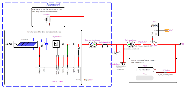
EMTP® model of an aggregated PV park
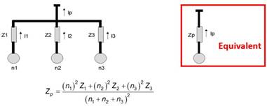
The aggregation methods for typical collector grid configurations are:
- The series daisy chain

- The parallel connection of branches
The converters can be modelled with a detailed representation which includes the PWM commutation of the IGBTs or with an Average Value Model (AVM) where the converter is modeled by three controlled voltage sources on the AC side and a current source on the DC side. AVM can be simulated with a larger time step. User can easily switch from a detailed converter model to an average value model.
Wind turbine model
Large-scale wind parks (WPs) employ variable speed wind turbines (WTs) in order to increase energy capture, reduce drive train stresses and comply with grid code requirements. Doubly-fed induction generator (DFIG) and full converter (FC) WTs fall into this category. The EMTP® built-in models contain the Max Power Point tracking (MPPT) functions which adjust the turbine speed and pitch angle for an optimal power generation.
 and the power conversion coefficient")
Maximum Cp curve as a function of the blade tip speed (Lambda) and the power conversion coefficient Cp for different blade pitch angles. These curves enable the wind turbine control to select the right pitch angle at every wind speed, while keeping the turbine in the safe operating mode.
PV cell model
The PV cell is modelled to reproduce the power-voltage characteristic.

The model is an equivalent electrical circuit with one nonlinear diode:

A database of thousands of PV cell manufacturers is available.
Why Renewable Energy Systems must be studied?
If not properly analyzed, the integration of large-scale Wind and Solar parks could lead to non-optimal operation of the plants, as well as severe issues in power system operation and stability. To avoid this, a range of different time-domain simulation studies must be performer, including:
- Switching overvoltages: the charging capacity of the collector grid cables can create overvoltages due to the lower system resonance frequency.
- Transient Overvoltages (TOV): TOVs in parks are more severe than in traditional distribution networks. One of the reasons for this is that the converters may remain momentarily energized after an islanding. Single-phase-to-ground faults must also be studied and the grounding system sized accordingly. High speed grounding switches may be used to mitigate TOV. The operation of these switches can be precisely modeled in EMTP®.
- Harmonic analysis: it is required to make sure that the harmonics injected into the network do not affect the voltage at the PPC. The harmonics in the voltage must remain within the limits defined by the standards (IEEE 519). Excessive harmonics can interact with the existing resonant points in the grid and cause issues such as extra losses and torque pulsation.

Results of an EMTP® study indicating an excessive magnitude of the 22nd harmonic in the inverter current
- Grid code requirements: the frequency and reactive power support of manufacturer models can be assessed as well as the Low Voltage Ride Through (LVRT) and Overvoltage Ride Through (OVRT) requirements. The overall grid performance can be verified with very precise models.
- Sub-synchronous Control Interaction (SSCI): SSCI is a sub-synchronous resonance due to the interaction between converter-based device controls of, but not limited to, wind parks, PV parks and HVDC, and the rest of the network. It can result with a severe voltage build-up and the risk of it occurring needs to be evaluated at different wind speed/irradiance conditions and network topologies. Because the behavior of such apparatus is non-linear, their frequency response cannot be assessed with frequency-domain frequency scan technics. The frequency scan must be done in time-domain, using the Time-domain (TD) input impedance device in EMTP®.

Frequency scan results indicating a positive equivalent resistance of the network (with the wind park connected) at the resonance frequency (of about 29Hz), showing therefore no risk of SSCI.
- Stability analysis: the grid stability and especially the interaction between renewable energy and synchronous generators which have very different dynamic must be assessed. Contingency analysis must be performed and protection system settings adjusted.
Why use EMTP® for Renewable Energy Systems studies?
EMTP® provides a comprehensive set of devices and control libraries allowing you to assemble and analyze detailed EMT models of renewable energy plants.
Here are the main advantages:
- EMTP® contains built-in, customizable Wind and PV park models, allowing you to readily define all the components of the system, such as the number of turbines or PV arrays, their rating, reactive power control at POI, MSC and GSC parameters, Coupled/Decoupled Sequence control options, parameters of the overcurrent protection, crowbar, etc.

Menu of the EMTP®’s built-in Wind park model

The content of these models is accessible and customizable!
- A harmonic model is available. The model automatically adjusts the harmonic magnitude and phase of each inverter, based upon the load flow simulation results for a given level of irradiance or wind.

- A model for each simulation type: The park models automatically adjust for load-flow, time-domain and frequency-scan simulations. No user intervention is required.
- Manufacturer model: manufacturers can build and share very detailed models. These models can be built with the EMTP® control library or with a code in the DLL format.
- Circuit contents can be password protected.
- A dedicated tool is available to perform SSCI analysis.
- Besides its transient solver, EMTP® comes with a load flow and steady state solvers. This enables to perform an automatic network initialization which makes transient analysis of DG parks in EMTP® extremely straightforward to set-up.
- A fast time-domain solver: EMTP® has a very advanced sparse matrix solver which allows to effectively simulate detailed Park models or to perform large grid simulations.