Version 4.5.0 - June 2024
- Improvement of GFM converter
- negative sequence control is added to GFM
- VI control is added to GFM
- Amplitude current limiter is added to GFM
- Some parameters are defined to converter control mask of GFM
- version 1.3 of GFM generated
Removed the c letter in converters, added GFM letters to GFM symbol

Figure 1:Control properties for GFM converter
- New licencing options
- User-based license option is now available. Instead of a license key, users can use a combination of an email address and a password to activate the license.
- Python scripting
- New examples and documentation available.
- Minor changes:
- Parallel processing: it was impossible to generate the slave objects when multiple subcircuits were selected. It is now possible.
- New location of HTML/blackbox/script_black_box_d.dwj
- New Script.DevObj added for easy scripting:
- cap_d.dwj
- ind_d.dwj
- lc_d.dwj
- res_d.dwj
- rl_d.dwj
- rlc_d.dwj
- rlc_m.dwj, includes correct _d selection
- rlcload_d.dwj
- Constant device script updated to the newest standard with _i, _d, _m, _p script files. c_cst_info.dwj is deleted.
- Gain device script updated to the newest standard with _i, _d, _m, _p script files. c_cst_info.dwj is deleted.
- update_variables_in_black_boxes.dwj has new waitbar option.
- Statistical: Changed window size
- Sw0_m: adjusted for incorrect deviation units when scripting
- FindDeviceAttributesFromLibrary.dwj: new function for looking for attributes
- statespace_d.dwj: added
- MMC_HVDC_link:
- Total Capacitor energy in converter and not Capacitor energy in each submodule
- Changed all MMC examples by removing incorrect attributes.
- vsine_m.dwj: Accounting for scripting with an unknown LF device name
- Several new services in make_file_name.dwj
- In simulation options, it is now possible to input a real number (not an integer, as before) for default frequency. This is for creating dc conditions.
- Corrected incorrect Sniffer in STATCOM
- Corrected incorrect Sniffer in GFM
- Corrected library name error: 2-level converter DM instead of 2_level
Version 4.4.0 - January 2024
- Change of licensing system. Cloud and floating cloud options are now available.
- Beta version of Python API. Same capabilities of JavaScript API are available.
- Possibility to print line/cable parameters in external files (.out), using the Mom-So based line/cable data calculator.
- New fitting options to solve cases with passivity issues
Version 4.3.1 - July 2023
Bug Fixing
Version 4.3 - June 2023
Exciters and Governors Toolbox Updates
Updates on the modules for improvement and to fix minor issues, including the non-windup integrator in the modules to follow IEEE Std 421.5-2016:
- Exciters: DC1A, AC3A, AC6A, ST7B, DC4B, ST1A, ST4B, ST2A, DC2A, ST3A, AC8B, AC7B, ST1, DC3A, IEEET5, IEEET1, SEXS, ST5B, ST6B, AC4A, AC2A, AC5A, AC1A, AC8C, ST2C, ST3C, ST4C, AC9C, ST3, AC2C, AC3C, AC6C, AC2, AC3, EXPIC1, AC1C, REXSYS, ST8C, ST9C, IEEET2, IEEET3, AC7C, AC11C, ST10C, AC10C, ST5C, ST6C, AC4C, DC1C, AC5C, DC4C, ST1C, EXPI;
- Governors: DEGOV1, HYGOV, HYGOV4, PIDGOV, WSHYGP, HYGOVR, GGOV1, IEEEG2, TGOV1, GAST2A, GAST, IEEEG3, IEEEG1, IEESGO, WEHGOV, TGOV5, WSHYDD, WESGOV, WEIEG1;
- Power system stabilizers: IEEEST, PSS3B, PSS1A, PSS2B, PSS3C, PSS4C, PSS2C;
- Synchronous machine phasors;
- Turbine load controller: LCBF1;
- Over excitation limiter: OEL1B, UEL1, OEL4C, OEL3C, OEL5C, OEL2C, UEL2C, MAXEX2;
- Stator current limiter: SCL1C, SCL2C;
- Voltage regulator: COMP, COMPCC, IEEEVC.
Renewables Toolbox Updates
- Development of new models:
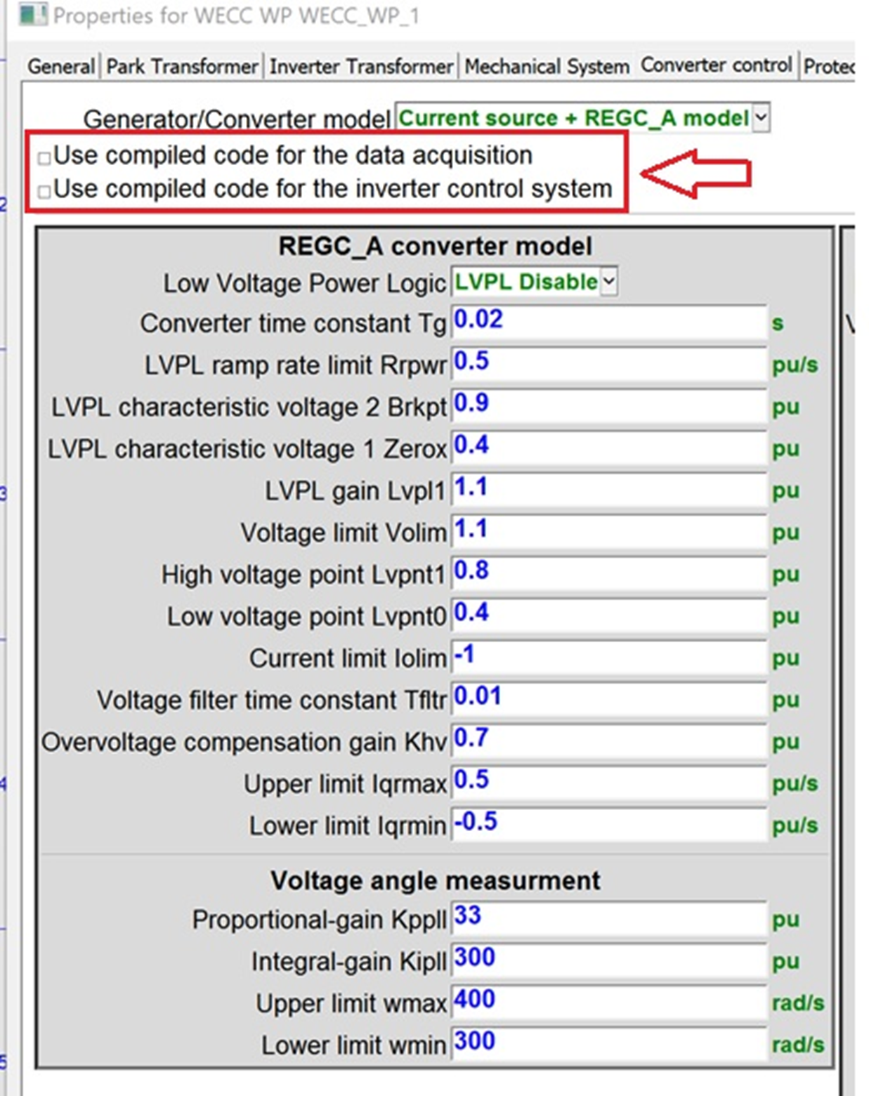
- WECC PV;
- WECC PV park;
- WECC Wind park;
- WECC Wind turbine


- A new option: use compiled block-diagrams to increase simulation speed available for:
- DFIG Wind Park
- DFIG Wind turbine
- FC Wind Park
- FC Wind turbine
- PV
- PVPark
- WECC PV
- WECC PVPark
- WECC Wind park
- WECC Wind turbine
- New examples were included in the library:
- EPRI_Aggregated_Park_WECC_PV_V1
- EPRI_Aggregated_Park_WECC_WP_V1
Power Electronics Toolbox Updates
- Development of Grid Forming Converter (GFM) with different control methods:
- Droop
- Virtual Synchronous Machine (VSM)
- Dispatchable Virtual Oscillator (dVOC)
- Phase-Locked Loop (PLL)

- Improved STATCOM model with two control modes, i.e., Q-control and VAC-control


- New examples were included in the library:
- GFMinverter
- IEEE_PSRC_D29_GFMinverter_V1
- IEEE_PSRC_D29_SM_V1
- StatcomV1
CIGRE IEEE DLL interface (New Library)
- Real-code:
- Exact copy of the real control system
- Original source code of a controller provided by the vendor/manufacturer
- Initialization feature
- New example was included in the library: SM_SCRX9
- License is required

Protection Toolbox Updates
- Development of “COMTRADE Recorder” and “COMTRADE Replay” based on IEEE Std C37.111-1999 and IEEE Std C37.111-2013

Lines Library Updates
- New Line/Cable Data Module
- Better visualization tool for geometry and content
- Zoom
- Panning
- Better information presentation


- Improvements in data input
- New options for saving impedance and admittance data
- Passivity violation: new code
- Existing examples were updated in the library
Sources Library Updates
- Development of five dependant voltage and current sources: current controlled current, current controlled voltage, current derivative controlled voltage, voltage controlled current, voltage controlled voltage

- Useful in various applications, including building of electromagnetic circuits using electric-magnetic duality.
Transformers Library Updates
- Development of amplifier module

Improved Performance of Control Solver
- New approach (option): reduce the numerical effort by applying relaxations (special new method)
")
Global Data Option
- New options are available to reduce time spent in updating global data for large cases (more flexible for users)

Netlist Generator Updates
- Improved to be superfast
Upgrade to version 4.4.0:
Customers under a valid maintenance contract can upgrade their license(s) to 4.4:
If you do not have an account on the EMTP® website or for any installation problem, please contact our technicial support team at support@emtp.com
Information for customers without a valid maintenance contract: If you wish to upgrade your license(s), please contact our sales teams:
| All request except USA | sales@emtp.com |
| USA | sales.usa@emtp.com |
| Local distributors | emtp.com/about-us/offices-distributors |
Version 4.2.1 - November 2021
Fixing bugs version:
- BCTRAN model : fix calculation issue when running the case in EMTP 4.2
- Hysteresis fitter : fix calculation issue when running the case in EMTP 4.2
- TRV breaker : unlock options which were unavailable in EMTP 4.2 TRV breaker
Version 4.2 - September 2021
New Line/Cable data module
- New module for calculation of line and cable parameters based on the MoM-SO method. This tool results from a major development effort by EMTP® team, and a direct collaboration with Prof. Piero Triverio and his research associate Utkarshr Patel from University of Toronto.
- Major new EMTP® module capable of achieving highest accuracy levels for a very large band of frequencies.
- The module is generic and capable of representing cables underground and above ground, overhead lines and overhead lines coupled with cables. A multi-layer soil option is available.
- The module accounts for proximity effect, stranded conductor and earth return.
- Unique contribution to the simulation of electromagnetic transients.

New Power Electronics Toolbox
- Various building components.
- New AC-DC converter with control.
- New Statcom model.
- New DC-DC AVM converter.
- New examples with Toolbox models.

Renewables Toolbox Updates
- Upgrades to PV and WTG models.
- Better initialization.
- Various improvements (generic models).
- PV cell.
- New Battery model.
- Improvement of convergence criteria for Input Impedance TD device.
- New example of PV converter with MPPT and battery.
- New charge/discharge battery example.

New Asynchronous Machine Database

Exciters and Governors toolbox Updates
News models available in the library:
- Exciters: AC1C, AC2, AC2C AC3, AC3C, AC4C, AC5C, AC6C, AC7C, AC8C, DC1C, DC4C, EXPI, EXPIC1, IEEET2, IEEET3, REXSYS, ST1C, ST2C, ST3C, ST4C, ST5C, ST6C
- Governors: WEHGOV, WESGOV
- Power system stabilizers: PSS2C, PSS3C, PSS4C,
- Stator current limiter: SCL2C
- Voltage regulator: IEEEVC
Transformer model improvements
- New magnetization data option: it is now possible to use excitation test data directly in voltage and current (pu).
- Air-core inductance value may be entered as an option for adding an extra segment to magnetization data.
- Tap ratio input is now available.
Improvements to PQ load with load-flow
- Allows Delta connexion.
- New input options:
- Positive sequence Data or 3-phase data
- Connection type
Breaker for TRV model improvements
- IEC 62271 - IEEE C37.013 standards are now available for System source fault, generator source fault and Load-current switching.
- New example of Generator TRV.
- New example of maximum degree of Asymmetry determination for Generator.
PSS®E import tool improvements
- Custom device usage option: allows to import a user-defined device
- Import only specific part: allows user to import only specific part(s) of the RAW file.
- Read-only option licence available.
Simulink module for EMTP® update
- Compatibility with Matlab 2021a
Version 4.1.3 - October 2020
Improvements
1 . Fixed an issue with web pages not showing correctly on some computers.
2 . Further upgrades to PSS/E tool.
Version 4.1.2 - September 2020
Improvements
1. Copy paste action cancelled in L nonlinear device when no data or data error from the data calculation device.
2. Copy paste action cancelled in ZnO arrester when no data or data error from the data calculation device.
3. The View Steady-State device button is not needed anymore and has been moved to the ribbon.
4. Option for enabling load-flow or steady-state visualisation in View Steady-State.
5. Account for new circuit case when automatic refresh of load-flow or steady-state solution is occurring without selections in View Steady-State device.
6. Place all devices from Lib: fixed an issue when invisible device exists in the design.
7. Moved MPLOT help to MPLOT folder.
8. New option for automatic transition from load-flow to time-domain simulation or frequency scan simulation.
9. New script for preparing parametric studies: prepare_parametric_case.dwj.
10. New scripts for parametric runs: startemtp_userunemtp.dwj and starte_emtpwithoptions.dwj.
11. Upgrades to template file.
12. New Cable database.
13. New PSS/E tool.
14. Various changes in Input Impedance TD: changes to fix memory issues and incorrect behaviours in some cases.
Version 4.1.1 - July 2020
Improved Simulate ribbon with keyboard shortcuts and options for following Load-Flow with Time-domain automatically.
New View Steady-State ribbon menu for simplifying selections.
New View Steady-State data extraction scripting options. New amplifier model
A new power amplifier model that can be used for aggregation of wind farms and other renewable energy sources. It is solved simultaneously with network equations: no time-step delay! The amplifier is available in both 1-phase and 3-phase versions.
Renewables Toolbox
Various improvements in performance and presentation. New built-in options for selecting scopes. New detailed wind park example.
Improvements to impedance scanning tool (Input Impedance Time-domain) for detecting unstable conditions with integrated renewables or for extracting equivalent impedances from complex networks. This powerful tool uses perturbation technique in time-domain computations for extracting positive sequence impedances for a specified range of frequencies. It is now faster and more accurate!
New amplifier device for easy park aggregation.
Meters library
Several changes for easy transitions between 1-phase and 3-phase versions. Rearranged naming for consistency. Redesigned symbols for less visual space. New meters: see 3-phase version of “Power: p(t) and q(t)” for calculating the sums of individual phase powers and new “Voltage scope”.
Fault device: new inductance option.
Examples: new GMD (Geomagnetic Disturbance) test case based on IEEE-118.
Version 4.1 - September 2019
New Renewable Energy Toolbox
This advanced Toolbox brings a variety of building blocks and tools for studying the integration of renewable energy sources into power systems.
The Type-III and Type-IV wind turbine models have been redesigned to improve automatic initialization and performance. A new Harmonic model tab is now available. The Harmonic model equivalent provides fast means for frequency-scan, steady-state and time-domain simulations and for determining harmonic distortion levels.
New and sophisticated Photovoltaic (PV) system models allow to study aggregated PV parks as well as individually connected arrays. A large manufacturer database is available and allows a single-click selection of PV module parameters. The Harmonic model option is also included for PVs.
Both detailed and average-value converter versions are available for PV and wind turbine models. All protection systems and standards are now fully customizable.
An advanced yet easy-to-use Scanning tool provides means for detecting and studying subsynchronous control interaction (SSCI) problems with inverter based systems. The scanning tool is generic and applicable to arbitrary network configurations with power-electronics control systems. SSCI may occur, for example, between a Type-III wind turbine control system and the series-compensated transmission line to which the wind park is connected. Not only the wind turbine control parameters, but also the wind park operating conditions can be varied to detect abnormal SSCI conditions.
New Library Power Electronics
This library provides several models and building blocks for commonly used converter systems. Various rectifier and converter models are provided in detailed and average-value versions. The detailed nonlinear IGBT model can be used to build accurate converter circuits. This library is establishing the basis for new developments to be released in upcoming versions.
Other improvements
1. A new Transient Recover Voltage (TRV) circuit breaker option now allows to automatically calculate the cleared short-circuit current input field. The TRV analysis plots can now be visualized in a single-click.
2. A new Fault device is now available in the Switches library. It is combined with the new Short-circuit ribbon to simplify various fault setting conditions at arbitrary nodes. It includes an Arc Reignition model and provides means for Random fault timings with the Statistical Options.
3. A new "Sample in File" device allows to collect simulation results at arbitrary locations and save into user-defined files for various visualization purposes. A sample enabling pin can control the sampled intervals.
4. The new "AC voltage source and impedance" device provides various means for entering short-circuit powers and currents with X/R ratios.
5. Several new Load-Flow and Steady-state phasor visualization options have been integrated to provide better messaging, data refreshing when navigating between subcircuits and reporting into Excel files. It is now possible to save all current phasors in addition to voltage phasors.
6. The EMTP® GUI has been upgraded with various new scripting options and methods.
7. The Protection Library license is no longer required for on/off-delay devices. Devices of this family which are included in EMTP® designs from previous versions must be updated to remove the license requirement.
Version 4.0.2 - November 2018
- New ScopeView 2018b.
- New documentation for ScopeView.
- New MPLOT: fixes some bugs.
- Improvements and upgrades to TRV breaker.
- Improvements to View Steady State option.
- Now the global option (Device Steady-State options) allows to eliminate previous selections. It will also refresh automatically.
- Fixed a bug related to automatic detection of voltage base when the system is very unbalanced.
- ZnO: fixed a bug for requesting energy observables.
- Wind generator models: fixed a bug related to checkboxes. The checkboxes were remaining on even when off was requested by users.
- Wideband line/cable model: fixed a memory leak. The model was not running for some cases with many phases. This was actually a compiler bug.
Version 4.0.1 - August 2018
- Fixed a bug that was causing the Quick Find tool to freeze in some large designs.
- Fixed a bug related to the device Ideal unit m-windings transformer. It was not working in 4.0 due to a script error with protection method. This issue could be important also for protected wind turbine or other manufacturer models. This issue was related to the internal method copyProtectionData.
- Fixed a bug related to Wideband Line/Cable model when using the Statistical option.
- Added two new devices in Exciters And Governors: WSIEG1 and MAXEX2
- Corrected the example case network230LFSM.ecf. It was causing an error due to Statistical option. Also same copy with Exciters And Governors Toolbox.
Version 4.0 - July 2018
Highlights
- EMTP® 4.0 contains many improvements on several fronts.
- The GUI EMTPWorks now allows to draw diagonal signals (at any angle) and offers new line editing features. This will simplify the drawing tasks for large scale transmission and distribution grids.
- The new View Steady-State tool offers many new load-flow and steady-state visualization options.
- The new Wideband transmission line and cable model with its new fitter is a major milestone. It delivers the most stable and accurate model in the industry for switching and lightning transients. It also delivers higher accuracy for DC cables in HVDC transmission.
- The new TRV breaker contains the TRV standards in its mask and simplifies engineering tasks for TRV simulation and analysis.
- The new line differential relay allows protection engineers to setup and test line relays to avoid spurious tripping during line energizations, current transformer saturation, etc.
List of new features
- Line Styles - allows signal lines to be displayed with a variety of bold colours and patterns to highlight function or status
- Diagonal Lines and Line editing features - allows more flexibility in signal line drawing
- Unicode String Format - EMTPWorks can now be adapted to any international language so users can display notations in their own language and use many special symbols
- Many new customization features, script methods
- New View Steady-State tool: shows sequence currents and phase currents, automatic subnetwork view, new reporting features
- Changes and improvements in devices (upgrades in data input)
- Better support of high resolution screens, including 4K
- New MPLOT version
- New Wideband Line/Cable models: new fitter and new model, more stable, more accurate, the most efficient and accurate model!
- Changes and improvements for Line Data and Cable Data functions
- New L-nonlinear and ZnO data functions: simplification of user tasks
- Improvements to CP-Line (data input) and new CP-line GUI
- New Toolbox for Controls of Synchronous machines: new set of exciters and governors
- Updates to Wind generator models.
- TRV breaker
- New CVT model with ferroresonance filter
- New line differential relay model
- Simulink toolbox: various improvements
SAMPLES
Graphical User Interface
- Line Styles - allows signal lines to be displayed with a variety of bold colours and patterns to highlight function or status
- Diagonal Lines and Line editing features - allows more flexibility in signal line drawing

- Unicode String Format - EMTPWorks can now be adapted to any international language so users can display notations in their own language and use many special symbols

View Steady-State
New View Steady-State tool: shows sequence currents and phase currents, automatic subnetwork view, new reporting features.

Models
- The new Wideband transmission line/cable model with its new fitter is a major milestone. It delivers the most stable and accurate model in the industry for switching and lightning transients. It also delivers higher accuracy for DC cables in HVDC transmission.
- Eliminates numerical instability problems!
- More accurate initialization!
- New fitter!


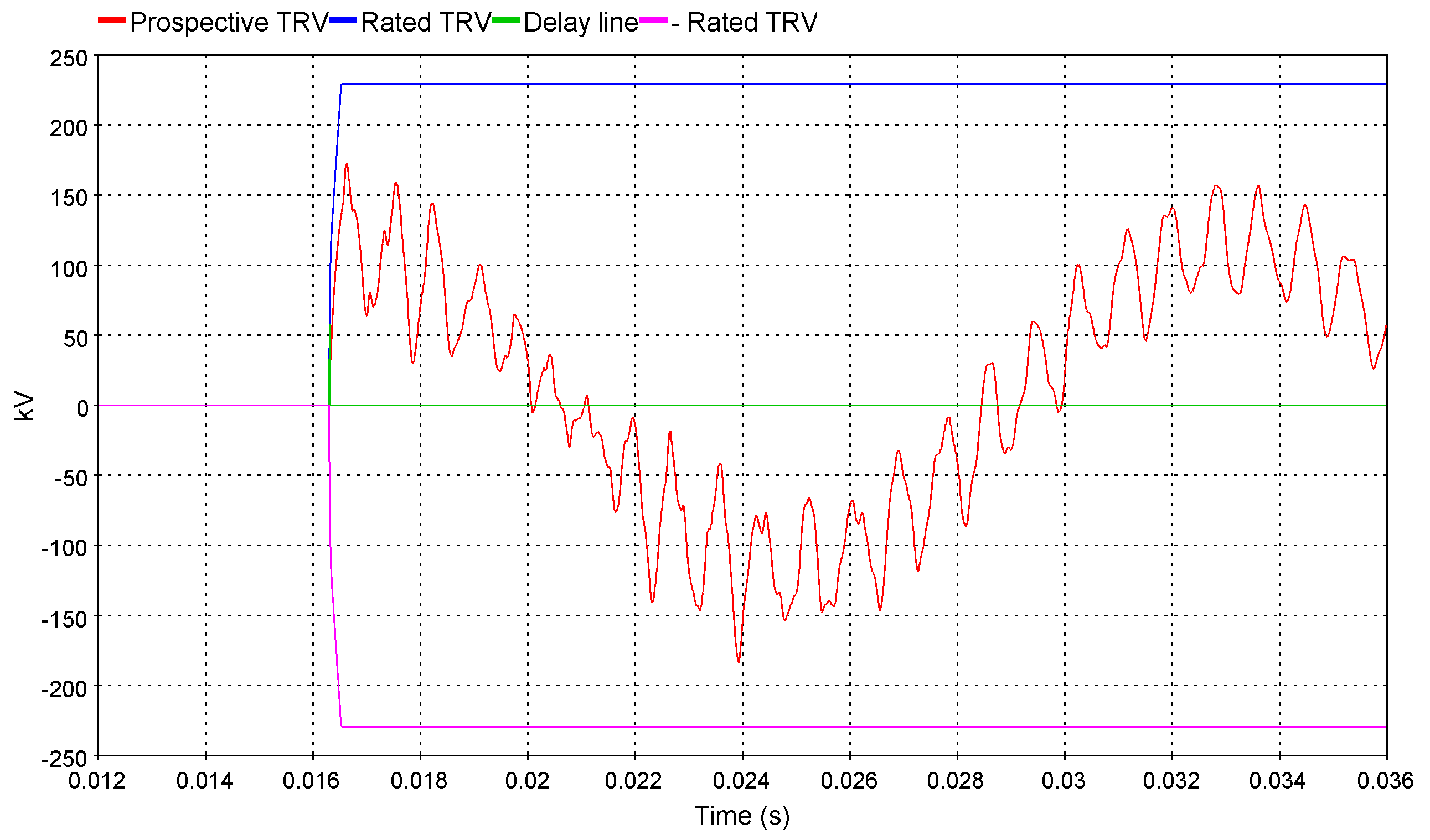
New TRV breaker: TRV studies made easy!
The new breaker for TRV helps engineers to interpret their TRV simulation results.It draws on the same graph the system prospective TRV obtain by EMTP® simulations with the circuit-breaker rated TRV obtain from IEC 62-271-100-2008 and IEEE C37.006-2008 standards.Without any efforts, engineers can complete the full TRV analysis without having to interpret the circuit-breaker standards.
New line differential relay model
The new line differential relay allows protection engineers to accurately verify their relay settings toward challenging scenarios like line energization or current transformer (CT) saturation.They even have the option to display the Alpha Plane to verify the restraint.


Version 3.5 - May 2017
EMTP® is constantly being improved to achieve highest accuracy levels and computational performance. New models and features are added to deliver to the users the most up to date analysis capabilities for modern power systems. Applications include small and large scale power system problems.
1. New Wind Turbine Models
- New DFIG and FC models with masks
- Improved control systems and new Wind Park control option
- Aggregated and detailed model options
- New practical benchmarks including subsynchronous interaction cases
- Examples for wind integration into practical power systems

Figure 1: New DFIG Wind turbine user interface

Figure 2: Detailed and aggregated models are available
2. New Line Database
- Large Database of conductors and tower configurations accessible from Line Data module
- Possibility to create and maintain user defined database

Figure 3: Line Database
3. New Harmonic source model with harmonic impedance
- For Frequency Scan, Harmonic Steady-State and Time-Domain simulations

Figure 4 : New harmonic source model user interface
4. New control devices
- Comparator (hysteresis)
- Deadband
- Manual switch
- Filter (LP-HP-BP-BS)
- On/Off delay
- Stop function: allows to interrupt the simulation given a criterion

Figure 5: New control devices
5. Updates for the Exciters and Governors library (separate module)
New models include: PSS4B, DC4B, ST5B, ST6B, ST7B, IEEET1, TGOV5, GGOV1, HYGOVR, WSHYDD, WSHYGP, HYGOV4,HYGOV, IEEEG2, PIDGOV, LCFB1
6. New IEEE-118 benchmark
7. New version of IEEE-39 benchmark with realistic data and electromagnetic Disturbance Case
8. Various improvements, including
- New zoom function for data input panels
- Improvements for eliminating the proliferation of useless attributes
- New Design ribbon commands for listing attributes
EMTP® Installation Requirements
- Windows Vista, Windows 7 or Windows 8
- Internet Explorer 6 or higher
- Pentium III 800 MHz CPU or better
- Minimum of 256 MB of RAM
- 500 MB of hard-disk space for installation
- Screen with a 1024x768 resolution or higher, 16 or 32 bit color quality, 96 DPI
Version 3.4 - August 2016
1. New models
New detailed Current Transformer (CT), Voltage Transformer (VT) and Capacitive Voltage Transformer (CVT) models are added to the «Transformers library» in both 1-phase and 3-phase versions. The models are based on IEEE and ANSI standards and include nonlinear properties (saturation).

3-phase CT in a network with protective relay

CT model user interface
2. EMTPWorks improvements
Bundles are easier than ever! It is now possible to connect directly into bundles without using breakouts. New options allow to create and modify connection pins and signals. The new «Bundle Connection» window make easier the connection and routing of bundles containing numerous signals. It helps the user to efficiently build complex multivariable control systems.

New bundle-to-bundle connection window. Colors represent the status of the connection

Bundle to signal connection without breakout
Other new features include:
- New capability to handle rotations of pictures in device symbols
- New option to maintain connections and reroute lines when rotating devices
- New option for maintaining connections when building subcircuits
- New option to check device name uniqueness
- General improvements in progress bar operation, displaying text title with percent bar
- Improvements in port connector placement and orientation in «Make Subcircuit» command
- Better presentation and options in symbol preview panel
- Many new scripting methods for various applications, including design, device and library functions.
- New example showing how to export automatically simulation results in a Matlab® data file (.mat)
3. FMI Toolbox
 standard compatible")
EMTP® is now compatible with the Functional Mock-up Interface (FMI) standard.
The aim of the FMI is to standardize data exchange between different simulation tools.
The list of compatible tools is available on www.fmi-standard.org and includes :
- Amesim®
- Dymola®
- Simulink®
- JModelica.org®
- LabVIEW®
- And others
EMTP® is compatible with the FMI Standard for co-simulation as master (version 1.0 and version 2.0) and as slave (version 2.0). It is an easy to use interface between prototyping tools like Matlab/Simulink® or Modelica® and EMTP® which let you benefit from the best of each environment.

FMU from Dymola in EMTP®
4. New additional Toolboxes (require specific licence)
Protection Toolbox
This new toolbox opens new doors for the simulation and analysis of protection systems. Both steady-state and time-domain simulation options are available. All relay, fuse and thermal element models are solved in time-domain with nonlinear functions, such as CT, VT and CVT magnetization. This new implementation for EMTP® allows to achieve highest levels of accuracy for protection coordination and analysis of performance with highly accurate power system models.
The power system may include many details ranging from power electronics models, HVDC transmission models and wind generation combined with traditional generation and transmission. There are no limitations! The relays can capture transients, harmonics, and various effects from power electronics based device controls.
Setting protection systems for renewable energies is finally made easy with the new EMTP® Protection Toolbox. The user can study any power system including inverted based devices for coordinating power-swing detection, distance protections, the interruption of currents by current-limiting fuses or determination of transformer differential protection settings.
Exciters and Governors Library
This new Exciters and Governors library contains 30 standard models for governors, exciters and power system stabilizers. It includes various models from the IEEE Standard 421.5-2005 “IEEE Recommended Practice for Excitation System Models for Power System Models for Power System Stability Studies”:
• Exciters: AC1A, AC2A, AC3A, AC5A, AC6A, AC7B, AC8B, DC1A, DC2A, DC3A, IEEET5, SEXS, ST1, ST1A, ST2A, ST3A, ST4B
• Governors: DEGOV1, GAST, GAST2A, IEEEG1, IEEEG3, IEESGO, TGOV1
• Power System Stabilizer: PSS1A, PSS2B, PSS3B
• Excitation limiter: Over Excitation Limiter OEL1B, Under Excitation Limiter UEL1
The models are built to be easily interfaced with Synchronous machine models in EMTP®.
Each device comes with its own user-interface, comprehensive documentation, and is automatically initialized from EMTP® steady-state and load-flow solutions. The control diagram of each device is fully customizable. New exciter, governor and stabilizer models are being added continuously and will become available in the future releases of this toolbox.
LIOV Toolbox
The LIOV (Lightning-Induced OverVoltage) code allows the calculation of lightning induced overvoltages on multiconductor lines above a lossy soil as a function of the line geometry, lightning current waveshape, stroke location, return-stroke velocity and soil electrical parameters. In order to deal with distribution networks having complex, realistic topology and configuration, the LIOV code has been interfaced with the Electromagnetic Transient Program (EMTP®).
The LIOV code has been validated by means of several experimental data, related to natural and triggered lightning experiments, and by means of Nuclear Electromagnetic Pulse Simulators and reduced scale models. The analysis of more complex system configurations composed by several lines and power components can be dealt with by using the LIOV EMTP® module.
Simulink Toolbox
The new Simulink® Toolbox allows to import any Simulink® models, regardless of its complexity, into EMTP® designs using two clicks. Minimum intervention from the user is required and the procedure only takes few minutes!
Using the appropriate Matlab® / Simulink® toolboxes and a compiler, a DLL is automatically created and used by this import tool to create the EMTP® model with all the necessary connections (pins). Vectors, complex and real signals can be interfaced with EMTP®. It is also possible to define tunable parameters in the Simulink® model and to assign them in EMTP®.
This Toolbox streamlines many complex tasks for building and exporting models built in Matlab / Simulink®. The Simulink® based models can be rapidly connected to complex EMTP® networks and benefit from the available and unique computational performance and models for large scale power system simulations.
Version 3.3.1 - June 2016
- New demo version (does not require a licence) limited to 60 devices
- Major new option for iterating with “R nonlinear controlled”: - This option is useful for the development of very accurate component models using control diagram blocks interface with the power network. - It is now allowed to iterate with control diagrams and network equations until a specified convergence tolerance. - It will open the door to research and development of advanced/accurate models using block diagrams.
- Load-flow options: - Further enhancements to help with convergence problems - New feature for user-defined specification of power transmission symbols - New feature for selections of PQ visualization settings
- New option for adjusting/specifying all attribute positions in the Symbol Editor
- New help system for opening pdf documentation directly
- Bug fixing and various minor enhancements
Version 3.3 - January 2016
1. Symbol Editor
- New option for pasting images (Enhance Metafile Format (EMF)) from external applications into the Symbol Editor.

- Added ability to specify attribute location in symbol editor by graphical placement.
2. Improvements to library functions:
- New symbol preview window for library devices.

- New double-click option for adding devices into design
- New option for specifying Library Title
3. Various improvements
- Documentation
- Improvements in error checking and reporting in user-defined scripts.
- Enhancements to XML script object: allow modification of attribute values, extraction of updated XML, creation of XML with direct XML text.
- Various improvements in show/hide/close operation of tool panels.
- Enhancements to improve handling of Unicode characters in text values, design files and libraries.
- New option for limiting the number of floating network fixes.
- New option for saving HTML voltage data only for nodes connected to ideal switches.
- Added new warning messages for inadvertently shorted voltage sources, transformers, switches and load-flow devices.
- Changes to allow the transmission of very long character strings when developing masks for the f(u) device (controls).
- Improved error messaging for named values.
- Various other improvements and bug fixing.
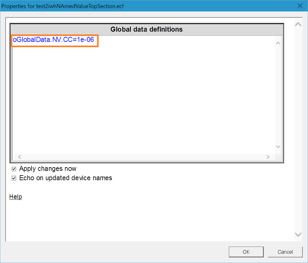
4. New option in “Define Global Variables” for specifying named values (parameters) for the top design (in addition to subnetworks).

5. Load-Flow
- New system for helping the user to identify devices/regions causing convergence problems due to data errors or else.

- Automatic transition to PQ control from PV control with messages for devices with Q limit violation.
6. New options for specifying predictors in controlled voltage and current sources to improve accuracy

7. DLLs
- New option for using dynamic names for user-defined DLL parts: allows to combine DLL calls and easily exchange data between DLLs of the same type.
- New search options for locating DLLs for Toolboxes and user-defined DLLs.
8. New ScopeView version
9. New option for better compatibility with high-resolutions screens

10. New automatic update feature
Version 3.1 - August 2015
- New docking tab systems with
- Floating design tabs
- Horizontal and vertical groups
- Display tool tip on document tab showing full path
- Ctrl-Tab command to cycle through tabs
- New Help Center
- New Licence Activation
- Various enhancements and fixes
- Minor improvements to symbol editor: phase and type selection options
- Display 1ph and 3ph pin types in Pin Info dialog
- Improvement to the auto-save option
- Improvements and upgrades to documentation
- Enhancements to XML scripting methods
- Enhancements to the handling of console windows: declaration and opening of separate consoles
- Enhanced Support for high resolution screens
- If your font size selection in Windows is more than 100% and your data input web pages are not showing all parts, you can now fix it using JavaScript commands
- See support web for more details
- New MPLOT
- 64 bit version for visualization of very large plot file cases
- New options
- New collection of examples:
- IEEE-39 test system with wind generation
- IEEE-39 test system with off-shore wind generation
- IEEE-39 test system for GMD studies
- Improved PV model
- Large grid wind integration benchmarks
- Line impedance modulator
- Transmission line and cable examples
- Basic power electronics applications
Version 3.0 - November 2014
- Major upgrade to the graphical user interface:
- Several new features
- New menus
- Usage of Windows style ribbons
- New library view
- New design tab system
- Better user interaction and significantly increased productivity!
- New View Steady-State option: XML based steady-state data, XML data scripting, new options for visualization of voltages and PQ powers.
- New distribution test case.
EMTP® demonstrates its unsurpassed capabilities for distribution systems in its IEEE-390 bus benchmark setup for distribution systems with network protectors. EMTP® has unique simulation options for distribution networks and is capable of seamless transition from multiphase load-flow to time-domain solutions. - New collection of examples:
- IEEE-39 bus system with new exponential load model
- Asynchronous machine stall example with mitigation with new STATCOM model (detailed and average value model options) and upgraded SVC model
- new IEEE-390 test system for distribution systems with network protectors
- 3-bus benchmark: demonstrates performance of wind generation as compared to conventional generation
- Transient stability: new real and largsystem test case for transient stability
- New PV model
- Wind generation: upgraded Type-III and Type-IV models, new generic wind park model, new examples
- New ScopeView version
Version 2.6.1 - May 2014
- The RLC device now has the R(f) function in Frequency scan mode.
- Fixed updating speed problems for attributes (phasors) in designs
- Changed all ideal switch type device models (complete library of switches) for sending a warning message when a switch-type device is shorted using a wire or by signal name. In this version if a shorted switch-type device is closed, it will be forced to open.
- All devices are now uniformly showing scopes for all options.
- Fixed server licencing issue.
Version 2.6 - December 2013
- A new set of load-flow and steady-state web options for visualization of results. The new options are available under the menu EMTP®>Simulation Options>Output. In addition, all devices and signals are now presented using the full subnetwork path (without subnetwork identification codes).
- Changes to device names in libraries to facilitate navigation and selection of devices.
- Upgraded wind generator model of DFIG type: improved controls, new protection features, simplified transition from average value to detailed model versions.
- New wind generator model of FC type: both average value to detailed model versions are available.
- Upgraded MMC-HVDC model with documentation.
- Offshore wind farm model with MMC-HVDC.
- Various improvements: improved PQ-load device, uniform presentation of Scope and Observe tabs, improved documentation by generalizing PDF based documentation instead of HTML, automatic copy of selected scopes/observables when moving from 1-phase to 3-phase device versions.
- New protection system for licencing devices/libraries through the licence file. This is a major change in the software file format.
Version 2.5 - August 2013
- Full compatibility with Windows 8 and the new Microsoft Surface Pro
- Full compatibility with Microsoft Internet Explorer 10
- New ScopeView R2013a with various improvements
- New MMC-HVDC model
- Improved DFIG wind generator model
- Improved convergence for the “ R nonlinear controlled” device
- Enhanced EMTPWorks script debugger: now shows error location for nested script calls
- Various other enhancements.
Version 2.4 - August 2012
In order to meet the growing needs of studies related to HVDC and renewable energies, the new version of EMTP® offers a larger library of application examples that includes power converters, wind turbines and HVDC networks.
New features:
New and advanced HVDC models, including MMC-HVDC
New wind generator models, including average-value model
New control system diagram DLL capability
New Simulink Coder (formerly Real-Time Workshop) interface DLL
Version 2.4 improvements:
Improvements in synchronous machine model including a new black start option
Improvements in the asynchronous machine model
Capability to solve multiple frequency load-flow
Improved documentation and various other improvements
Many new application examples
Version 2.3 - January 2012
New features:
New EMTPWorks version with various improvements including the simplified handling of bundle signals.
New ScopeView version with various improvements.
New installer for better support of 64 bit protection.
Full compatibility with the most recent Microsoft and Intel compilers for DLL development. Simplifications in the DLL debugging procedures.
Various improvements to the numerical precision of synchronous and asynchronous machine models for a given integration time-step. Improvements in the modeling of saturation.
Numerical improvements for Wideband Line and Cable models
Dramatic improvement in computational speed for the load-flow solution method, more than 20 times faster!
Version 2.2.1- July 2009
New features:
Full compatibility with Vista.
New documentation system including new navigation features.
Various improvements and additions to models.
The data handling features for numerous models have been simplified to allow for easier loading with separately calculated data.
New capability to store complete circuits in libraries.
- A circuit appearing in a library folder now becomes listed in the library Parts,
- Palette and can be dragged and dropped into a design just like standard parts. This is a very powerful feature that provides easy access to user circuits and allows you to maintain more complex models through libraries.
Subcircuits are now given the Model or Physical attribute in the Subcircuit Info menu.
- A model subcircuit is primarily intended to define the operation of the device represented by its parent symbol.
- A physical subcircuit is primarily used to contain some of the system.
- The devices inside the subcircuit represent actual physical elements of the system.
- The physical subcircuit may contain Model subcircuits.
- This distinction allows propagating computed data into Physical subcircuits for visualization purposes.
Several new scripting methods, including dynamic modification of device symbol using a separately stored symbol drawing.
New and improved ScopeView package.
A new HVDC benchmark (for 50 Hz and 60 Hz networks) originally developed by Professor Vijay Sood (University of Ontario Institute of Technology) is now available upon request.
This work was prepared in collaboration with Sébastien Dennetière (Électricité de France) and École Polytechnique de Montréal.
Version 2.1- October 2007
EMTP® now supports the integration of DLLs, enabling EMTP® users to become developers of their own customized version of the program.The new DLL capabilities or unsurpassed potential for building user-defined models:
New features:
The DLL is totally independent from the EMTP® code.
- You can use any programming language capable of generating standard DLLs. - Any number of DLLs can be used in a given design and use totally arbitrary names and locations on your computer.
There is no need to link with the EMTP® code. You just follow the DLL plug-in standards and specify in EMTPWorks.
The DLL plug-in standard for EMTP® is basically a set of specific methods that EMTP® will try to discover by interrogating the DLL.
You can create models that can interact intimately with EMTP® computation methods.
- This means that you can program “truenonlinear” (iterative) models, models that become fully integrated without any time-step delay into the EMTP® main system of equations and control models for receiving and sending control signals from a black-box type device.
- The DLL can have control pins and power pins and any number of pins!
- It can use your own symbol and data input design.
Basically, you can develop and use models as if you were an EMTP® developer!
The available capabilities will open the door to the development of advanced models in addition to providing an extremely powerful environment for research on new solution techniques and models.
- It is now possible to build advanced devices and test them within large scale practical networks assembled in EMTPWorks.
Another important feature in 2.1 is the ability to locate errors directly on the design page:
Now when you get an error message:
- Click on it
- A device name appears with a dynamic link
- Click on the device name and it will show you where the device is located on the screen!
Version 2.0.1
New features:
New Device Protection.
This option, available through the Symbol Editor,is a major change in EMTPWorks that required a very large number of code changesin all device maintenance options and scripting techniques.
It allows encryptionto protect device content from access and/or modification.
This is a very useful optionfor protecting subcircuit contents and for hiding proprietary contents from users.
Passwords can be easily entered and maintained by the original users who develop the encrypted devices.
Password protection is available at any hierarchy level.
New design file format.
Due to the introduction of the Device Protection option explained above, it is no longer possible to open
Version 2 files in previous versions of EMTP®. This is also true for new libraries.
New drawing and editing tools.
Various shapes can now be drawn and edited directly on the drawing of the design.
These tools can be used for documenting the design and representing specific design regions.
The shapes created can be modified, colored, and layered over existing schematic symbols.
New toolbar customization option.
New options in “Make Unique Type” command.
It is now possible to apply the command to all subcircuit contents.
This is an easy method for completely detaching a subcircuit and all its contents from all other subcircuits of the same type.
The new command and all its options are also available through scripts.
All devices with scripted masks now programmable.
The programming uses device object data and methods.
This means, for example, that the data of a built-in 3-phase transformer can be modified from any upper-level mask.
Many new script methods for services and enhanced programming techniques.
New State-Space device for power systems.
This device allows entering state-space equation matrices and solving state-space equations simultaneously with electrical network equations.
New State-Space device for control systems.
New transformer ratio control option.
New load-flow or steady-state visualization option.
Load-flow phasors can be placed on the schematic (“View Steady-State” in options.clf).
New options for the Frequency Scan feature.
It is now possible to perform a frequency scan and match source frequency.
Improved error messaging and testing of user errors.
A large number of changes have been made to enhance these functions.
’Using EMTP® – Tutorials and Reference’.
This document is now also available in PDF format, accessible from the online documentation and can be printed for offline use.
Addition of several advanced models in the Examples library:
Long air gap leader model for insulation coordination studies
On-load tap changer model for voltage stability studies
Secondary arc model for single-pole switching
Multi-chamber HV circuit-breaker arc model (Cassie-Mayr-Modified)