Microgrids are relatively small systems in size but high in complexity. They can operate grid-connected or islanded. In the latter case, they do not benefit from the power and frequency support of the grid and maintaining their stability becomes a challenge due to the lack or the low inertia. Often, generation is distributed and inverter-based which forces to setup protection systems accordingly and to ensure a acceptable power quality.
What challenges EMTP® answers?
· Because of their low/lack of inertia, microgrid frequencies may vary during disturbances. Microgrids also display non-linear behaviors due to inverter-based device controls. Therefore, for many microgrid applications, an iterative time-domain solver is required to reach an acceptable precision.
· Stability studies evaluate interactions between different distributed generation (DG) controllers and synchronous generators.
· Power quality is a big challenge because of the weakness of microgrids and the high penetration of inverter-based devices. Assessment of voltage and frequency drop/rise, analysis of harmonic contents and flickering must be performed in islanded mode and in grid-connected mode.
· Unbalanced power flow within the islanded microgrid needs to be analyzed to achieve optimal power sharing in islanded mode.
· Protection coordination of a microgrid needs to be performed in light of microgrid-specific characteristic such as bi-directional power flows and low available fault currents in islanded mode.
· To ensure a safe operation when a microgrid gets islanded, it is important to evaluate the performance of different strategies for islanding detection.
· Black start of a microgrid refers to its energization in islanded mode, following a blackout for example. Depending on the distribution of the DG resources and their black start capabilities, strategies must be simulated to determine the proper sequence of operations.
Why use EMTP® for Microgrid simulation?
· Time-domain iterative solver: even if they are called microgrids, their models are very large as a significant number of distributed resources and loads are present and may have non-linear behaviors. The advanced iterative sparse matrix solver of EMTP® is specifically designed for fast and accurate analysis of large and non-linear networks.
· Automatic initialization from Load-Flow results: because of the possible large number of DGs, initialization using power ram-up techniques is very challenging to achieved while keeping the simulation numerically stable. These techniques may also require a long computational time before reaching steady-state. EMTP® initializes time-domain simulations from the results of its unbalanced load-flow solver achieving a perfect flat start which saves a lot of time.
· EMTP® provides a specialized Microgrid Analysis Toolbox with built-in components allowing to assemble a detailed microgrid model, including inverters, batteries, PVs and wind turbines, as well as filters and control blocks for control system modeling.
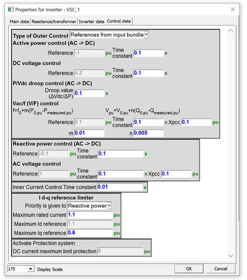
Menu of the EMTP® built-in inverter model – Control data tab
· EMTP® contains a versatile component library that streamlines the construction of custom inverter models. In addition to that, black-box manufacturer inverter models can be built reach maximum precision.
· The EMTP® controls library allows you to create detail models of microgrid control systems, including the islanding detection schemes, phasor measurement units, generator start-up sequence and synchronization.
· The EMTP® Protection toolbox provides advanced relay and fuse models as well as tools to perform protection coordination in steady-state or in time-domain.
The inverter model in EMTP®
Inverters can either be modeled in detail or as an Average Value Model (AVM). Detailed models consider the PWM modulation and detailed IGBTs. Their simulation requires small time steps. AVM replaces the inverter bridge with a 3-phase controlled voltage sources, significantly speeding up the simulation, while remaining accurate enough for many common studies.
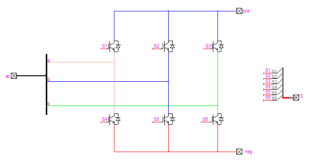
Detailed converter model
The converter control is modeled in detail with the measurement sampling and filtering, the Phase-Locked Loop (PLL), the regulation loops and the protection system. The regulation loops are implemented in the DQ0 reference frame which allows a decoupled control of the active and reactive power. A decoupling between positive and negative sequences can also be achieved.
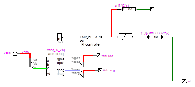
EMTP® generic PLL
The control is staged with a slow loop (outer) that computes the current reference values and fast loop (inner) that generates the AC voltage references controlling the converter.
There are four different outer loop control methods built in the EMTP® Inverter model: Active power control, VDC control, P/ VDC Droop Control and VAC/f control. VAC/f control is used in the islanded mode with the phase angle and frequency references generated from an internal oscillator, while the ac voltage magnitude is controlled by a PI controller.
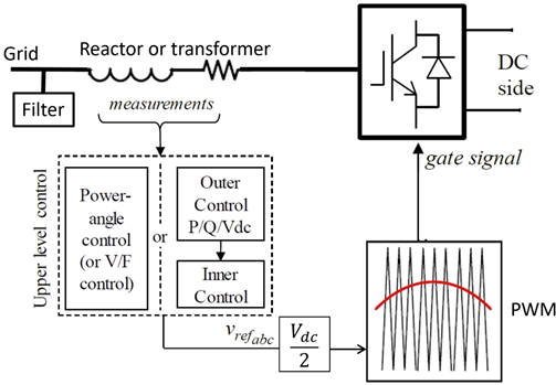
Control System diagram of a Voltage Source based Inverter
Like most models in EMTP®, the inverter is a white box accessible and customizable.
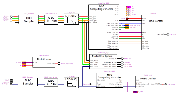
Full-converter control
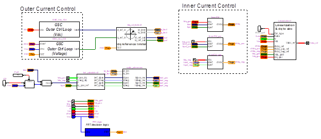
Grid side controller control scheme
