
High Voltage Direct Current (HVDC) transmission has emerged over the past few decades as an optimal solution for energy transfer in many applications. It exists two main HVDC converter technologies:
- Line Commutated Converter (LCC): Most of the HVDC converters in service today are of this type. The switching devices used in LCCs are typically thyristors and are arranged in a three-phase 12-pulse bridge configuration to reduce harmonics. The active and reactive power control of these converters is done by controlling the thyristor turn-on angle.
- Voltage Source Converters (VSC): VSC-HVDC technology uses mainly Insulated Gate Bipolar Transistors (IGBTs). The potential applications of VSC-HVDC systems include interconnections of asynchronous systems, grid integration of off-shore wind farms, electrification of remote islands, oil and gas stations, and multi-terminal dc grids. VSC-HVDC systems can independently control both active and reactive powers by maintaining stable voltage and frequency. which allows the supply of very weak grids and even passive networks.
Modular Multilevel Converter (MMC) technology uses series-connected half-bridge modules. It has overcome many limitations of other multilevel converter topologies for HVDC applications. MMC topologies allow using a lower switching frequency to reduce converter losses. In addition, filter requirements are eliminated by using a significant number of levels per phase. Scalability to higher voltages is easily achieved and reliability is improved by increasing the number of sub-modules (SMs) per arm.
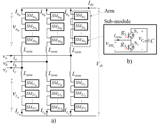
a) MMC topology b) Half-bridge converter of the i-th Sub-module
Reference:
N. Flourentzou, V. G. Agelidis and G. D. Demetriades, “VSC-Based HVDC Power Transmission Systems: An Overview,” IEEE Trans. on Power Electronics, vol. 24, no. 3, pp. 592-602, March 2009.
HVDC Station Model
EMTP® comes with a built-in, customizable MMC station model, that comes in two configurations: Monopole and Bipolar with earth grounding return. In addition to that, there are also pre-built LCC station models, that can be easily modified or rebuilt from scratch using EMTP® parts library.
Because these models have an open architecture, any configurations can be achieved.
 Monopolar HVDC transmission system and b) of the connection of two MMCs on one end of the Bipolar DC link")

EMTP® models of a) Monopolar HVDC transmission system and b) of the connection of two MMCs on one end of the Bipolar DC link
The HVDC station models are composed of:
· A step-up transformer that connects the AC grid to the MMC.
· The main AC breaker
· A star point reactor used to provide the ground reference to the MMC when the step-up transformer is Delta connected on the MMC side.
· AC converter breaker used for the start-up sequence.
· The converter
· The control and protection systems
· A harmonic filter.
LCC Converter Model
LCC 12-pulse converter essentially consists of two 6-pulse bridges connected in series. Each 6-pulse bridge is fed from two different windings (one is Wye and the other is Delta connected) of a 3-winding transformer with a 30-degres phase-shift (vs 60deg in a 6-pulse bridge) to achieve better harmonic suppression.

EMTP® model of 12-pulse LCC converter. Each thyristor switch is paired with an RLC snubber.
MMC Converter Model
Each phase arm of the MMC model is an assembly of several Sub-Modules (SMs) in series. SMs are half-bridge converters, containing a capacitor and two IGBTs with antiparallel diodes. Depending on the state of the IGBT switches, the SMs can either be in ON, OFF or blocking state.

EMTP® model of an MMC Sub-Module – when switch S1 (upper) is ON and S2 is OFF, the voltage across the SM equals the capacitor voltage Vc. When S1 is OFF and S2 is ON, the SM voltage equals zero. When both switches are OFF the SM is in the blocking state and its voltage depends on the current direction through the arm.
Depending on the type of study and the level of accuracy required, EMTP® offers 4 different MMC models with different levels of detail.
Full detailed MMC model includes non-linear model of every IGBT and diode in each SM. This model is the most accurate and can consider every conduction mode in the MMC. However, to accurately model simultaneous switching of multiple IGBTs, it requires a small-time step, which can be very computationally intensive. Full detailed models are usually used for advanced studies, prototyping of different SM topologies, and validation/calibration of simplified models.

Subcircuit breakdown of the Full detailed MMC-401 Level model in EMTP®
Detailed equivalent model replaces the IGBTs and diodes by small ON state resistance and large OFF state resistance, while the capacitors are replaced by an equivalent current source. This model significantly simplifies the circuit solution, while still considering each SM separately and individual capacitor voltages.
Switching function of arm model further simplifies the model by replacing the entire MMC arm with a switching function that calculates the total arm voltage and current based upon the number of switches in the ON state. It also assumes a uniform voltage distribution among the arm capacitors to replace them by a single equivalent arm capacitor Carm=C/N, where N is the total number of SMs in the arm. Switching function of arm model doesn’t represent the individual SMs, so the balancing control of capacitor voltages cannot be studies with this model, however, higher level phenomena such as the circulating currents and conduction losses are still considered.

EMTP® MMC models ranked by the decreasing resolution, from Full detail model, over Detailed equivalent and Switching function, to Average Value Model. The first two EMTP® models consider individual SMs, and they can be automatically set to either one of these MMC levels: MMC-401L (400SM/arm), MMC-101L (100SM/arm) and MMC-21L (20SM/arm).
Average Value Model (AVM) based on power frequency assumes that all SM capacitor voltages are perfectly balanced and that there are no circulating currents, so that therefore internal MMC variables are perfectly controlled. Each MMC phase is represented by a controlled voltage source, and the equivalent MMC capacitance is determined. The AVM model executes very fast and it is still suitable enough for many common studies.
- Talk to our team about pricing
- Get some technical information.
- Free consultation.
MMC Control System Model
Two different Upper level control strategies are built in the EMTP® MMC model: Vector current control and V/F control. In V/F control, the phase angle and frequency are generated from an internal oscillator, while the ac voltage magnitude is controlled by a PI controller. V/F control is used to connect a VSC to an AC grid with a passive load or in wind turbine applications.
Vector current control is used by the outer loop to control active and reactive power independently in the dq frame and compute the dq current reference for the inner loop controller. There are three different outer loop methods built in the EMTP® MMC model: Active power control, DC Voltage control, and P/Vdc Droop Control. The inner control loop computes the reference dq voltage signals that will be used for the Lower level control.

MMC Control System Diagram
Lower level control’s task is to stabilize internal MMC variables. It is composed of:
· Circulating Current Suppression Control (CCSC) - suppresses the internal MMC currents caused by the imbalance between the phase voltages
· Nearest Level Control (NLC) modulation - a technique that handles well MMCs with high number of levels
· Capacitor Balancing Algorithm (CBA) - aims at balancing the SM capacitor voltages and decides which SMs to switch ON.
Why HVDC Systems must be studied?
The behavior of an integrated HVDC system under different load and fault conditions will depend on the complex interaction between the converter and the AC network. To accurately evaluate performance of this highly non-linear system, the simulation must be performed in time-domain. Some of the most important time-domain studies for an HVDC system include:
· Initial system analysis at the planning and specification stage allows engineers to identify any potential issues and propose solutions. For this type of analysis, customizable, general converter models (like the one provided in EMTP®) or the black-box models from manufacturers can be used.
· To evaluate manufacturer algorithms. In this case, manufacturer models which are replicas of the real control software should be provided. These models are very often black-boxed to protect the intellectual properties.
· Analysis of the HVDC control interaction or resonance with the system should be performed to evaluate risk of potential instabilities.
· Fault studies needs to be performed for a variety of fault types, locations, and active and reactive set-points, to determine the worst-case scenario current surges and voltage sags.
· Harmonic studies
· Protection performances can be precisely assessed using the EMTP® Protection Library.
Why use EMTP® for HVDC System studies?
EMTP® offers you a versatile simulation platform, with highly customizable devices and control libraries allowing you to assemble and analyze detailed models of HVDC stations in a variety of operating conditions and fault scenarios.
· EMTP® contains built-in, customizable MMC Station models, allowing to readily select how detailed the model needs to be, select the control strategy, define all the components of the system, including the number of MMC levels, step-up transformer properties, SM IGBTs and capacitors etc.

Menu of the EMTP® built-in MMC station model

The content of these models is accessible and customizable!
· A model for each simulation type: the station models automatically adjusts for load-flow, time-domain and frequency-scan simulations. No user intervention is required.
· One major challenge when a grid contains several HVDC, FACTS or converter-based devices is the simulation initialization. EMTP® comes with load flow and steady state solvers which allows to find to the steady-state conditions and to automatically initialize the network. This simplify greatly transient analysis of HVDC systems.
· The wide frequency band transmission line and cable models have special feature to precisely DC. More information here:
· Parametric solver and scripting enable you to automatically run batches of simulation cases and perform statistical analysis of results and identify likelihood of certain scenarios.
· A fast time-domain solver: EMTP® has a very advanced sparse matrix solver which allows to effectively simulate detailed MMC models or to perform large grid simulations. A 401 MMC detailed model is available. This model contains almost 10000 IGBTS.
· Manufacturer models: Manufacturers build and share replica of the converter control models.