How to realize the following functions in EMTP-RV: 1) The frequency of the custom power supply changes every other cycle, and the frequency value is controllable; or a signal can be realized, which can achieve the frequency change every cycle
Frequency of the custom power supply changes every cycle
Hello,
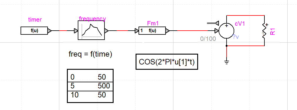
You can build a frequency variable source (voltage or current source) by using the controlled current/voltage source (library sources) and building the frequency variable signal with control devices.
Use a generator (constant, table function, signal generator) to generate the value of the frequency, then apply it to the "f(u)" device to rebuild the sinusoidal voltage/current using the equation.
See here an example.
Thanks a lot, this is a good…
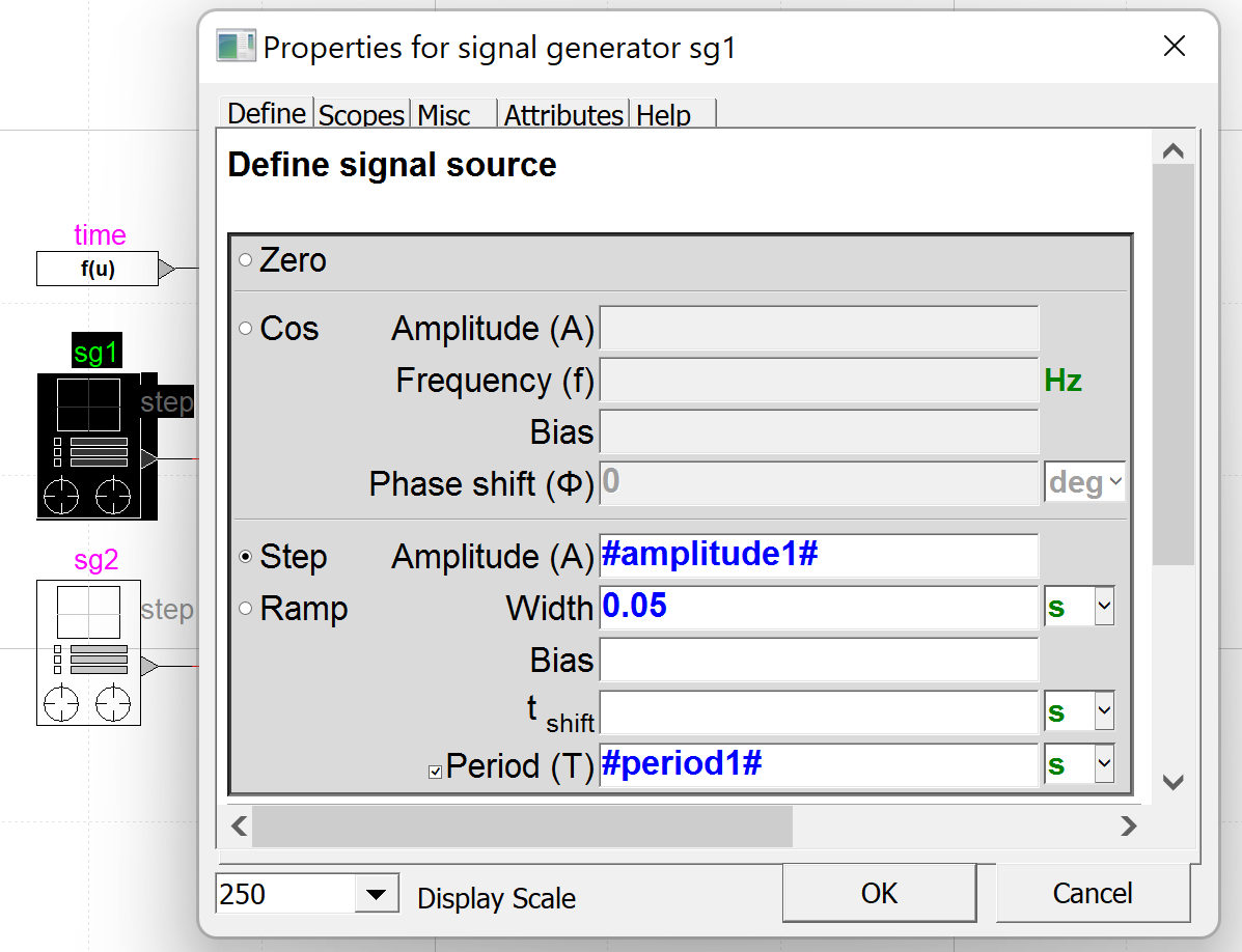
Thanks a lot, this is a good method, then the same method should also be used to generate a square wave signal with variable frequency, but it seems less intuitive. The software provides a signal generator for generating a variety of waveforms, whether the signal generator can be used to generate square waves and sine waves with adjustable frequencies. As can be seen in the figure, there are multiple parameters for input. For such parameters, it is possible to define a variable other than directly using numbers?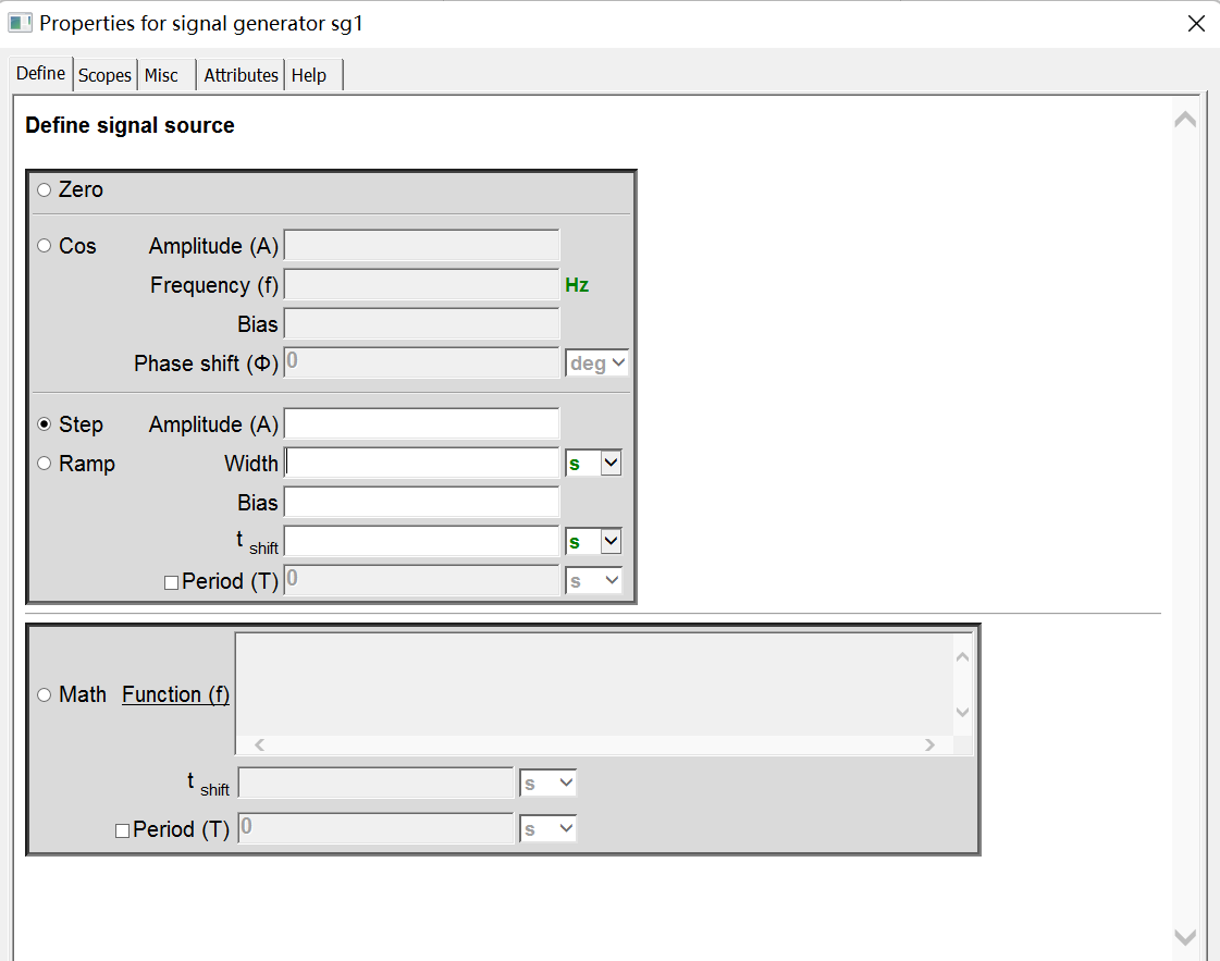
Subcircuit and Mask
Dear,
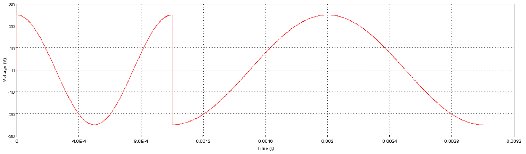
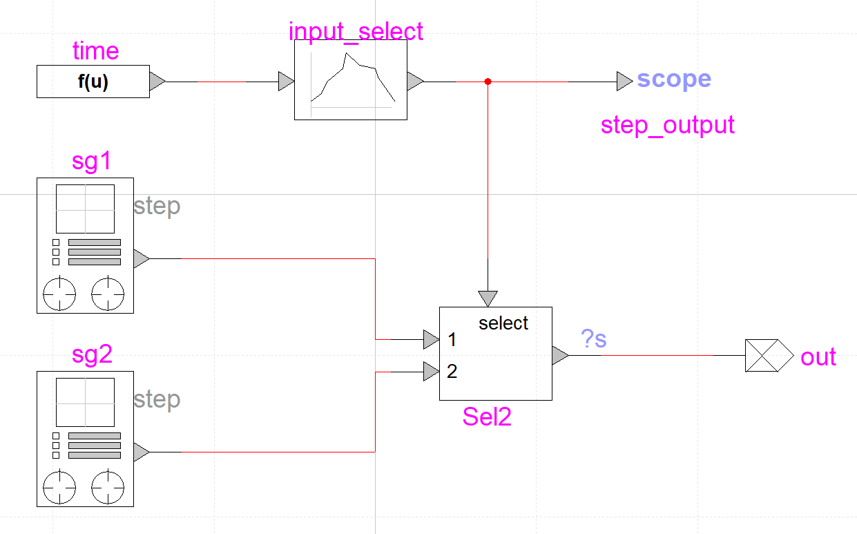
For you to generate a square wave with variable frequency, you can use multiple signal generators with different frequencies, an input selector and a table function responsible for selecting the desired input. Please, see the example below.
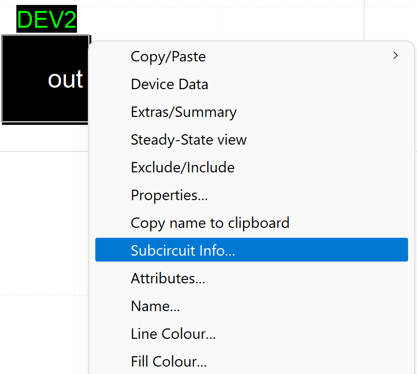
Instead of providing the values to the signal generator, you can create a subcircuit and a mask for the model.
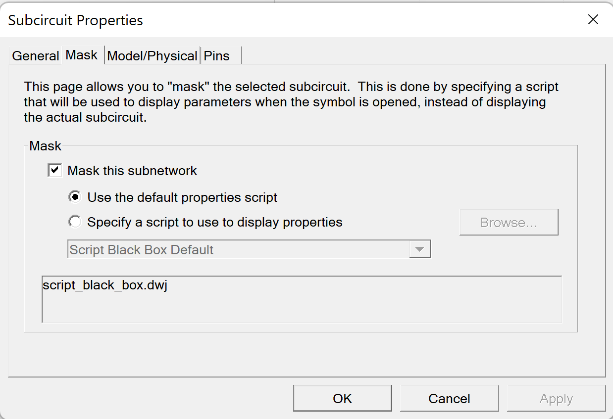
With the mask created, variables can be defined and transferred to the subcircuit. For that, the # must be used before and after the variable name.
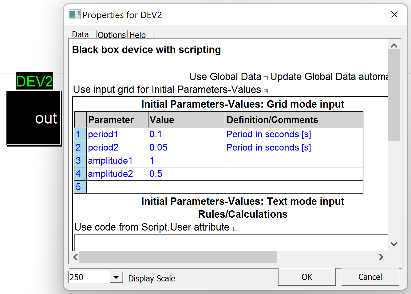
Please, see below an illustration of that. The variable 'period1', with value 0.1, is passed to its corresponding field as '#period1#'. The other variables follow the same pattern.
In the "EMTP User Manual" you can check section 5.3 - Tutorial 3: Creating a Subcircuit Bottom Up for subcircuit creation and section 8.12 - Masking for subcircuit masking.
https://www.emtp.com/documentation/emtp-user-manual#_Toc62212820
Yours sincerely,
Mauro