In this tutorial section we will look at how to use hierarchy to simplify the representation of
complex designs. Using this feature, a symbol on a top-level circuit can itself represent a
subcircuit of any desired size or complexity.
1. Isolate the part of the EMTP model that will make the subcircuit.
Figure 1: Example of a model
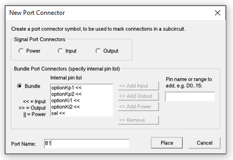
2. A subcircuit needs to have special symbols called "Port Connectors" which indicate which signals in the subcircuit are available for connection through the parent symbol.
In Options/Subcircuit, select âNew Port Connectorâ and create the different ports of your future subcircuit. Choose the types of the signal (power, input (for control signals), output (for control signals)), specify their names and connect the ports to the signals (as on Fig. 3).
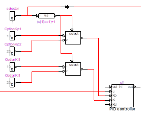
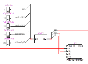
Figure 2: Subcircuit menu

Figure 3 : the circuit with the ports
3. Select all the devices and ports. You can select the entire interconnected circuit section using:
· the mouse pointer and selecting with a bounding box
· hold the Ctrl button and double-click on any one of the devices, it will select the entire (physically) interconnected circuit
4. Open the subcircuit wizard (Options/Subcircuit/Create Subcircuit Block).

5. In âQuick Subcircuitâ section, specify a name for the symbol. The symbol name is different than the device name which is an attribute of each instance of the symbol.
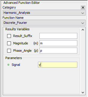
Figure 4 : Subcircuit creator wizard
6. Click Finish.

Figure 5 : the subcircuit after creation
7. You may modify the symbol (right-click on the device and âEdit Symbolâ)
See more information on subcircuit access and modification in EMTP: File/Help & Support/2 â Using EMTP â Tutorials and Reference\Chapter: Creating a Subcircuit Bottom Up
Masking is a powerful feature for data hiding and encapsulation. It provides a high-level access to subcircuit parameters and allows creating user defined models.
To mask:
1. right-click on the device and select âSubcircuit Infoâ.
2. In the Mask tab, select âMask this subnetworkâ and OK.
3. Now, when you double-click on the device, it opens the âBlack boxâ properties window. You can use it to manage the internal parameters on the subcircuit.
a. The âInitial Parameters Valuesâ Grid allows you to specify the values of the input parameters. Parameter column is for the names, Value for the parameter values. Comments are optional.
b. The âRules/Calculations sectionâ is used to make the connection between Initial Parameters (user input parameters) and the Parameters to transmit to models inside the subcircuit. JavaScript syntax is used in this section. The Math JavaScript object is included.
See the documentation in the Help tab for information on the syntax options.
c. The âVariables to transmitâ is used to specify the internal parameters of the subcircuit. These parameters must be specified in the subcircuit devices between â#â and using SI units (volts for voltage, Henry for inductance, â¦). Only certain basic components of the library support this option.
The mask Option tab provides options to hide sections or customize the black-box mask.
To access the subcircuit once the mask is created, hold Alt and double-click on the symbol. You may also use the push into option of the Options ribbon.
d. Below in an example: the mask (top), the subcircuit model (bottom left) and the internal switch parameters (bottom right)
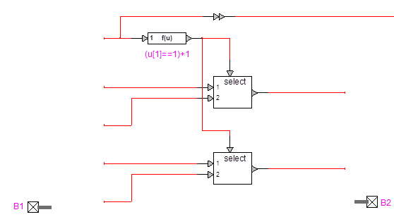
Figure 6 example of Black Box Window
![]()
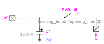
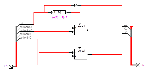
Figure 7 Subcircuit example