Access to EMTP user presentations, webinars, and slide deck presentations.
32 presentations for protection:
Author(s): N.K. Nathan
Type:Technical Presentation
Date: 2021-09-01
Abstract
Transient enclosure voltage (TEV) also known as Transient ground potential rise (TGPR) is a special case of VFTO. This phenomenon refers to short rise time, short duration high voltage transient which... see more appear on earthed enclosure of GIS. This is mainly through the coupling of internal transients on conductor refracted to the enclosure at enclosure discontinuities such as air terminations, insulated flanges at GIS/Cable interfaces and some current transformers. Primarily disconnector switch operations are causes of VFTO and SF6-Air bushing seems to be the most significant source of TEV.
Observation of sparking between grounded enclosure and support structure, failure of protective devices, inadvertent operation of relays etc are common malfunction of TEV. Despite proper grounding this phenomenon indicates presence of high potentials on GIS enclosures which raises the issue of equipment protection, migration of these transients to adjacent equipment and shock hazards.
TEV in 400kV GIS substation due to “disconnector switch operation” was studied and simulations performed for GIS model with the equivalent resistance of ground grid, resistance and inductance of grounding strip using EMTP. The presentation summarizes the results of study needed for a 400kV GIS substation in India to ascertain VFTO induced TGPR level. The study was carried out by modeling all GIS equipment, enclosure in EMTP and careful consideration of grounding system model. The results of the study were analyzed to decide on the requirement of mitigation methods to ensure the permissible level of TEV.
Tag(s): gis, vfto, very fast transient
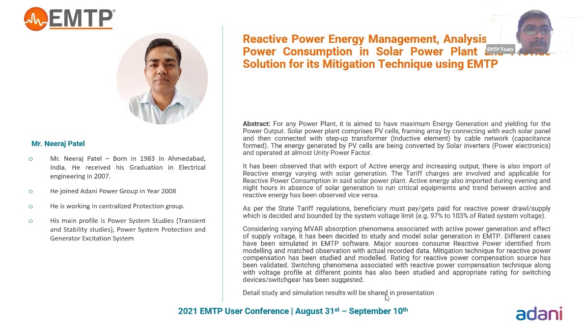
Author(s): Neeraj Patel - Adani Power
Type:Technical Presentation
Downloaded: 3
Date: 2021-06-21
Abstract
Unsuccessful auto reclosure has been observed in 765 kV HVAC transmission lines connected with Generation Bus. Back up Impedance Protection of Line reactor triggered during AR dead time due to power f... see morerequency oscillations in faulty phase (disconnected phase). It triggered tripping of Non Switchable Line Reactor at one end, which resulted tripping of 765 kV HVAC Line and avoidable Generation loss.
These Unsuccessful AR operations triggered us to study and model entire phenomena in Power System Analysis software (EMTP).
Initially, two circuits of 765 kV Transmission Line commissioned between Generation Station and Transmission Station with Line Reactor and NGR in both line at either end. Successful auto reclosure observed during single-phase faults on these lines. Intermediate Switching station constructed and both lines were divided in 4 section as per new requirement. Same configuration (rating) of Line Reactor and NGR adopted at newly constructed station on each line. Unsuccessful AR observed during AR running cycle on these lines after new configuration. Backup Impedance protection of Line Reactor found operated during AR Dead time.
Different sets of simulations has been carried out to understand the phenomena:
- Single Phase fault and Auto reclosure in 765 kV Transmission line in different section of entire corridor with Varying Shunt compensation (Value of Line Reactor)
- Different NGR values and observations for above simulations
- Trip the Line Reactor Breaker during Auto Reclosure Phenomena to avoid operation of Backup Impedance protection and its consequences
After EMTP Simulations and study, it was concluded that:
- Line Reactor (Degree of compensation) should be adjusted with adequate value while line length altered from its original design.
- NGR re-sizing can address the issues at some extent. Suitable value of NGR (based on Line Length and amount of shunt compensation) should be employed
Appropriate Solution and mitigation suggested after detail simulation & study.
Tag(s): single pole, analysis, auto reclosure, line reactor
Author(s): Dr. Sanjoy Kumar Parida - IIT
Type:Technical Presentation
Downloaded: 4
Date: 2021-06-21
Abstract
The complexity of an active distribution system with distributed generation (DG) is increasing day-by-day. Therefore, a reliable protection system is very necessary to satisfy customer demand. Apart f... see morerom main grid supply, active sources are also available near load centers due to which traditional protection schemes fails to function properly.
The magnitude of fault current during grid connected mode of microgrid, is much higher than islanded operation. Therefore, in most of the previous works, overcurrent protection crashes if its pickup current value is not changed when microgrid is shifted to islanded mode. In this work, the current, voltage and frequency data sampled through PMU is processed to protect the system in both the operating modes. A centralized protection scheme is employed that takes frequency data and voltage phasor to differentiate between islanding and fault condition. Further, it detects the faulted feeder and sends trip command to respective relays within a tolerant time.
This method is devised to work as backup protection when main utility grid is available. However, it can work as a primary protection during islanded mode, when local overcurrent relay fails to operate due to settings based on grid connected mode. A standard IEEE 15 bus system modeled in EMTP is taken as test system for every analysis.
Author(s): Paul VERRAX - SuperGrid Institute
Type:Technical Presentation
Date: 2021-06-17
Abstract
This presentation focuses on voltage and current sensors modelling and its application on a transient based protection algorithm within a 4-terminal HVDC grid simulated in EMTP.
Fully selec... see moretive protection strategies for meshed HVDC grids need very fast DC fault identification and isolation which constitutes one of the main locks for large deployment of such grids. Transient based fault identification algorithms based on the modelling of the voltage and current traveling waves are seen as a promising solution to achieve fast fault identification. In addition, such algorithms are able to estimate the fault parameters such as the fault distance using local sensor data.As a model based approach, the accuracy of the sensors may impact the fault identification results as well as the precision of the estimated fault parameters.
In depth sensitivity analysis for different parameters of the sensor are carried out to outline the influence of the sensor characteristics on the fault identification results as well as the accuracy on the estimated fault parameters.













![[R&D]_EMTP : Recherche et développement [R&D]_EMTP : Recherche et développement](https://www.emtp.com/system/files/imagecache/presentation/slide1_1.jpg)




![[Protection_Devices]_Étude des courants coupés par les sectionneurs de changemen [Protection_Devices]_Étude des courants coupés par les sectionneurs de changemen](https://www.emtp.com/system/files/imagecache/presentation/TechnicalPresentation1.jpg)
